Inkjet recording head and image forming apparatus comprising inkjet recording head

a technology of inkjet recording and image forming apparatus, which is applied in the direction of printing and inking apparatus, etc., can solve the problems of inability to perform ejection and suction of this kind during printing, nozzles subject to ejection failures, and ink ejection direction may be deflected, so as to prevent the occurrence of uneven meniscus surface or infiltration of air bubbles, stable ejection, and stable quality

Inactive Publication Date: 2009-07-14
FUJIFILM CORP
View PDF3 Cites 7 Cited by
  • Summary
  • Abstract
  • Description
  • Claims
  • Application Information

AI Technical Summary

Benefits of technology

[0016]The present invention has been contrived in view of the foregoing circumstances, an object thereof being to provide an inkjet recording head and an image forming apparatus comprising an inkjet recording head, in order to prevent the viscosity of ink at a meniscus surface from increasing, prevent ink having increased viscosity from entering a pressure chamber and carry out stable ejection.

Problems solved by technology

On the other hand, in an image forming apparatus of a line type ink ejection head which corresponds to the paper width and is suitable for high-speed printing, it is difficult to perform ejection and suctioning of this kind during printing.
Consequently, there is a possibility that the nozzles are subjected to ejection failures due to the nozzle blockages or disappearance of the ink in the nozzles.
However, this technology in the related art involves following problems.
Hence the meniscus surface shape becomes asymmetrical in accordance with the shape of the porous material, and hence the ink ejection direction may be deflected or ejection failures may occur because air bubbles enter the porous member.
Moreover, even if a push ejection method in which the ink is ejected by pushing without first pulling the meniscus is used in order to avoid such problems, residual vibration (resonance) of the meniscus after ejection, which also occurs in the pull-push ejection method described above, occurs.
However, in this case, air bubbles may be incorporated into the porous member, and thereby ink may not be ejected in the subsequent ejection operation.
In the related art, although drive waveforms have accordingly been designed so as to reduce residual vibration of this kind, it is difficult to eliminate the influence of residual vibration completely.
However, the above technology is not effective against the ejection defects occurring as a result of the viscosity increase during printing a single sheet or page.
Moreover, according to the above technology, the print speed declines because suctioning is carried out (if necessary) prior to printing a new sheet or page.

Method used


Image

  • Inkjet recording head and image forming apparatus comprising inkjet recording head
  • Inkjet recording head and image forming apparatus comprising inkjet recording head
  • Inkjet recording head and image forming apparatus comprising inkjet recording head

Examples


first embodiment

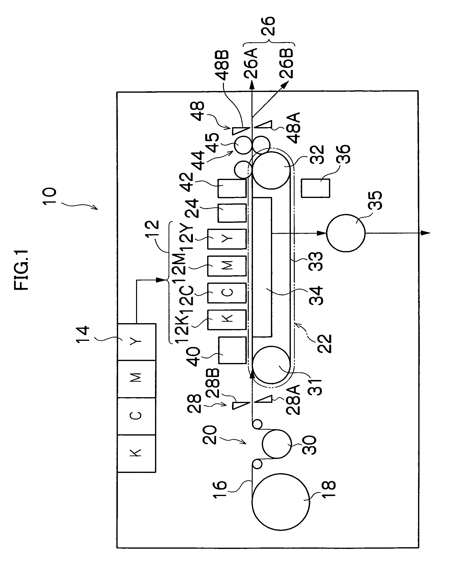
[0052]FIG. 1 is a general schematic diagram showing an approximate view of an inkjet recording apparatus having an inkjet recording head in the present invention.

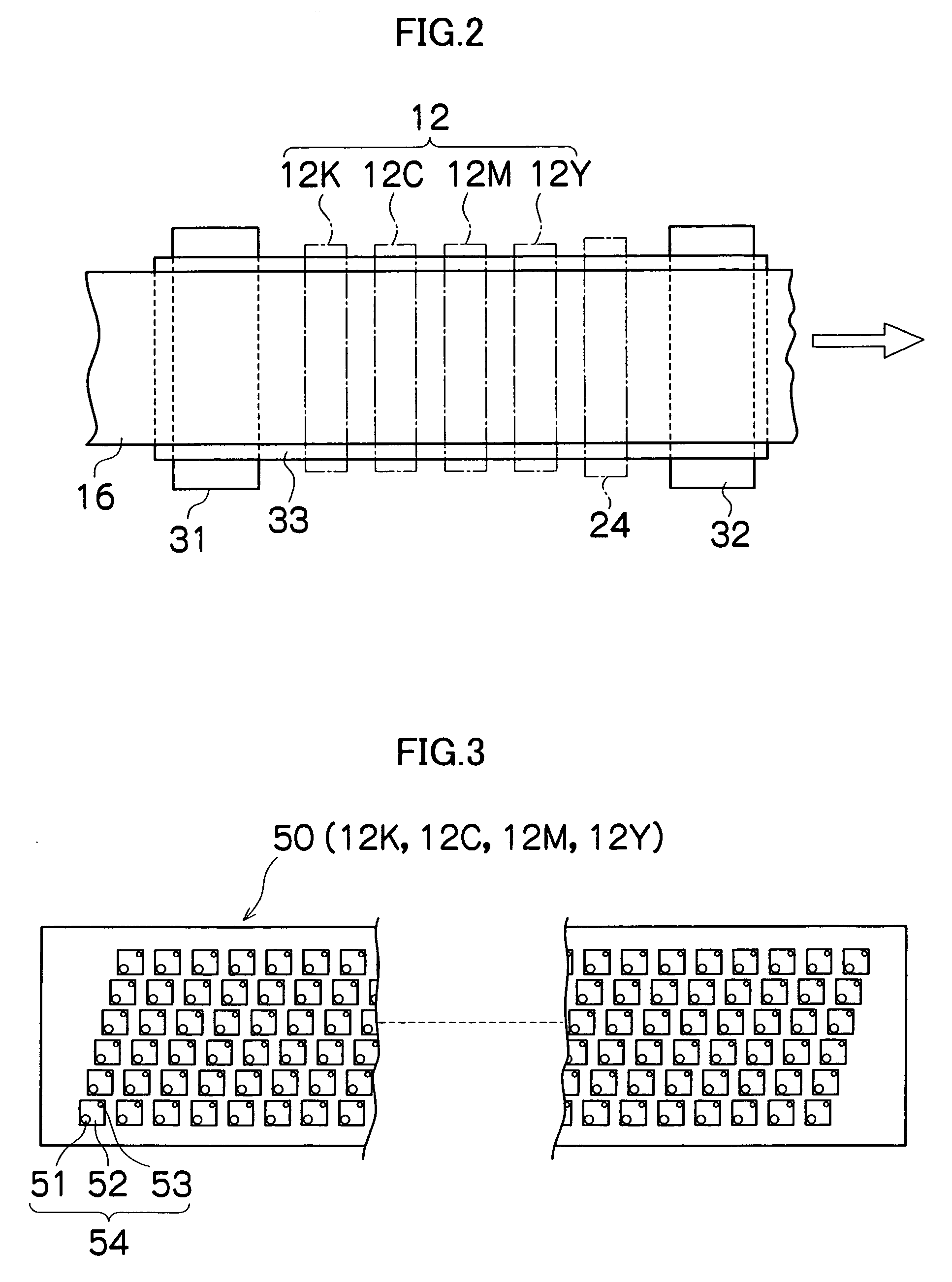
[0053]As shown in FIG. 1, the inkjet recording apparatus 10 comprises: a printing unit 12 having a plurality of print heads (inkjet recording heads) 12K, 12C, 12M, and 12Y for ink colors of black (K), cyan (C), magenta (M), and yellow (Y), respectively; an ink storing and loading unit 14 for storing inks of K, C, M and Y to be supplied to the print heads 12K, 12C, 12M, and 12Y; a paper supply unit 18 for supplying a recording paper 16; a decurling unit 20 for removing curl in the recording paper 16; a suction belt conveyance unit 22 disposed facing the nozzle face (ink-droplet ejection face) of the print unit 12, for conveying the recording paper 16 while keeping the recording paper 16 flat; a print determination unit 24 for reading the printed result produced by the printing unit 12; and a paper output unit 26 for outputt...

second embodiment

[0159]Next, a second embodiment according to the present invention is described.

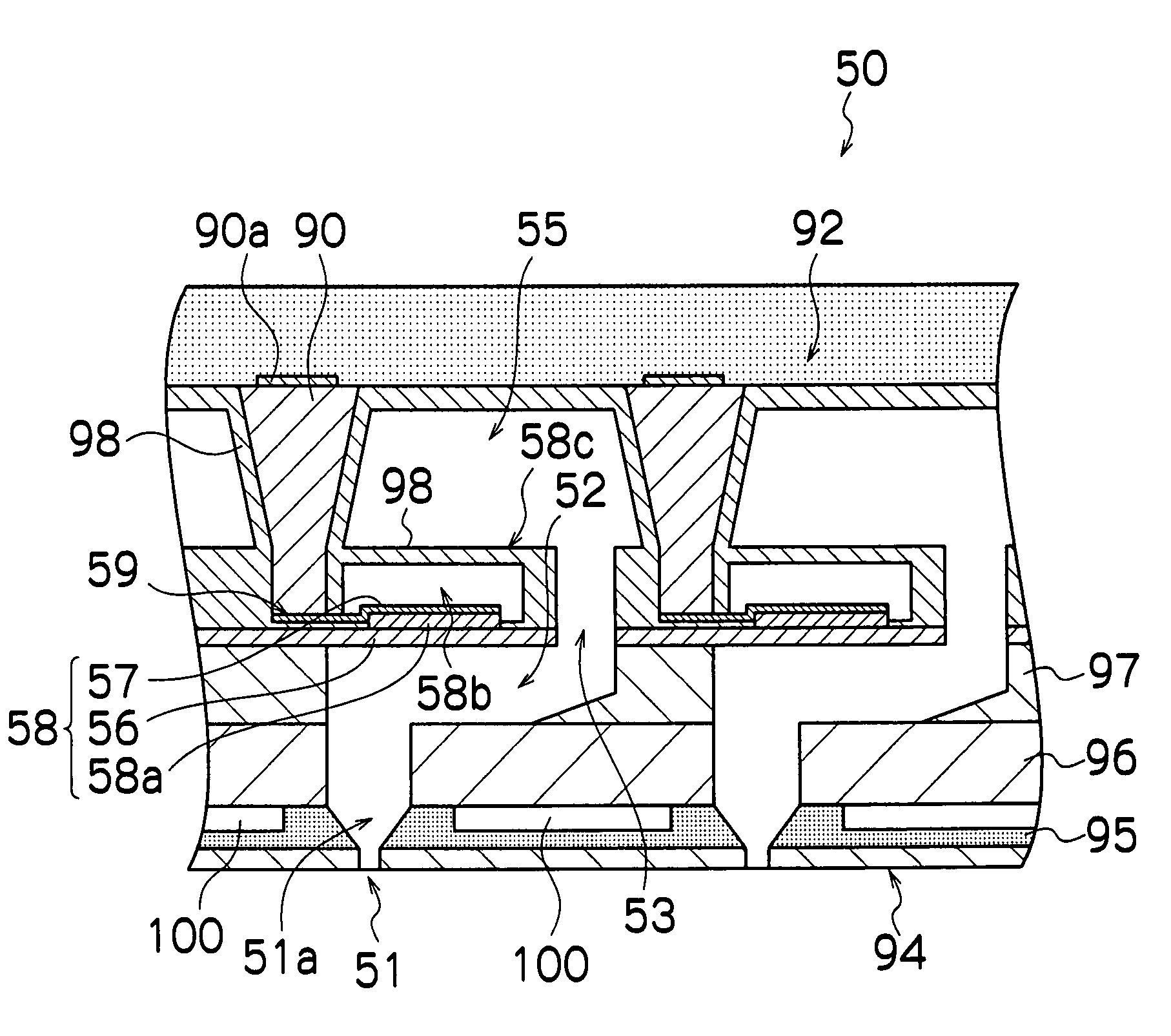
[0160]FIG. 16 is a cross-sectional diagram showing an approximate view of the vicinity of a nozzle in the inkjet recording head (print head) according to the second embodiment of the present invention.

[0161]As shown in FIG. 16, the print head 250 according to the second embodiment has a composition that is substantially the same as that of the print head 50 according to the first embodiment shown in FIG. 10, and furthermore, refilling supply channels 299 are provided in the nozzle flow channel plate (in the present embodiment, the nozzle flow channel plate 296).

[0162]The refilling supply channels 299 serve for refilling the ink into the nozzle flow channels 251 a after ejection. In order to supply the ink to the nozzle flow channels 251 a from the respective refilling supply channels 299, the relationship among the ink pressures is adjusted in such a manner that the ink pressure P4 in a refilling supply ...


PUM


Abstract

The inkjet recording head includes: a pressure chamber to which ink is supplied from an ink supply side; a nozzle plate including a nozzle which is connected to the pressure chamber and ejects the ink; and a circulation flow channel plate which is disposed on an opposite side of the nozzle plate from an ink ejection side, and includes: a circulation flow channel for expelling the ink from a vicinity of the nozzle; and a first nozzle flow channel for connecting the nozzle with the pressure chamber, wherein: at least a portion of the circulation flow channel plate is made of a porous member; a contact angle of the ink at an inner surface of the nozzle of the nozzle plate and a contact angle of the ink at an ink ejection side surface of the nozzle plate are greater than a contact angle of the ink at an inner surface of the first nozzle flow channel; and relationship among an internal ink pressure P1 in the ink supply side, an internal ink pressure P2 in the circulation flow channel, and an atmospheric pressure P3, is expressed as follows: P3>P1>P2.

Description

BACKGROUND OF THE INVENTION[0001]1. Field of the Invention[0002]The present invention relates to an inkjet recording head and an image forming apparatus comprising an inkjet recording head, and in particular, to maintenance technology for an inkjet recording apparatus which prevents the viscosity of liquid at a meniscus surface from increasing and enables stable ejection.[0003]2. Description of the Related Art[0004]As an image forming apparatus in the related art, an inkjet printer (inkjet recording apparatus) is known, which comprises an ink ejection head (inkjet recording head) having an arrangement of a plurality of nozzles and forms images on a recording medium by ejecting ink liquid droplets from the nozzles in the ink ejection head toward the recording medium while relatively moving the ink ejection head and the recording medium to each other.[0005]Various methods are known in the related art as ink ejection methods for an inkjet recording apparatus of this kind. For example, ...

Claims


Application Information

Patent Timeline
Patent Type & Authority Patents(United States)
IPC IPC(8): B41J2/045B41J2/175
CPCB41J2/04543B41J2/04588B41J2/04596B41J2/14233B41J2/1433B41J2/1606B41J2/175B41J2/17509B41J2/17566B41J2/04581B41J2202/21B41J2002/14459B41J2002/14491B41J2202/18B41J2202/20
Inventor KODAMA, KENICHI
Owner FUJIFILM CORP
Why Eureka
Try Eureka