Auto-adjust noise canceling microphone with position sensor

Inactive Publication Date: 2009-07-14
PLANTRONICS
View PDF11 Cites 62 Cited by
  • Summary
  • Abstract
  • Description
  • Claims
  • Application Information

AI Technical Summary

Benefits of technology

[0010]When incorrect positioning of the microphone is detected, the system and method in accordance with the present inven

Problems solved by technology

Often times, however, a user does not optimally position a NC mic, like that included in a communications headset.
The mispositioned NC microphone reduces sensitivity to the user's voice, and this in turn reduces the signal-to-noise ratio (SNR).
Severe misposition of the NC mic is also problematic because the user's voice will be attenuated to a degree that is unintelligible for the receiving entity (e.g., person or machine) on the other end of the communication link.
Whichever way the NC mic is formed, the problem remains that either angular mispositioning (i.e., polar pattern related

Method used


Image

  • Auto-adjust noise canceling microphone with position sensor
  • Auto-adjust noise canceling microphone with position sensor
  • Auto-adjust noise canceling microphone with position sensor

Examples


Example

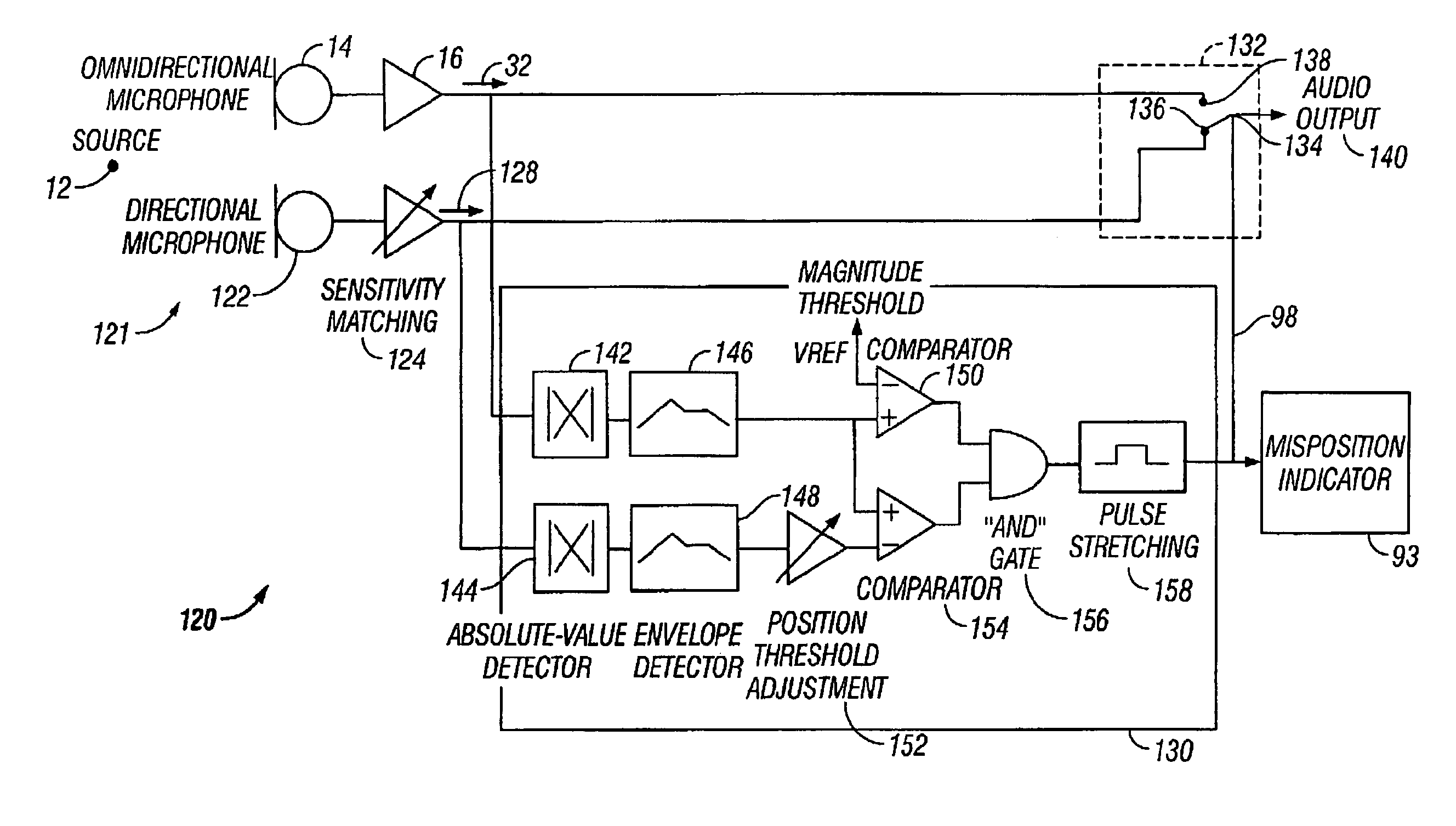
[0059]FIG. 5 illustrates a third embodiment of the present invention. Here, a microphone proximity correction system 120 includes a microphone assembly 121 comprising a first microphone 14 receiving acoustical signals from an acoustic source 12 and coupled to a pre-amplifier 16. Microphone assembly 121 further includes a second microphone 122 coupled to a sensitivity matching circuit 124. The sensitivity matching circuit 124 matches the microphones 14 and 122 according to a standard output, so that noise canceling characteristics may be facilitated. The first microphone 14 is an omnidirectional pick-up microphone as previously described, and the second microphone 122 is a directional NC microphone.

[0060]Noise canceling effects may be derived from a single microphone for the second microphone 122. In order to do so, the pair of pick-up points for a single microphone may comprise two openings (orifices) closely spaced together similar to how microphones 14 and 22 have been described. ...

Example

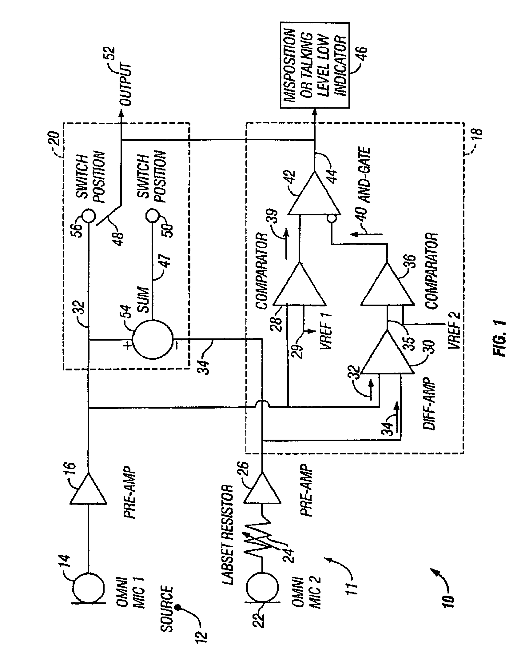
[0071]FIG. 6 illustrates a fourth embodiment of the present invention. Here, a microphone proximity correction system 160 includes a microphone apparatus 161. Microphone apparatus 161 is similar to microphone apparatus 11, and includes: a first microphone 14 receiving acoustical signals from an acoustic source 12 and coupled to a pre-amplifier 16; and a second microphone 22 coupled to a sensitivity matching circuit 125. The sensitivity matching circuit 125 is similar to sensitivity matching circuit 124 and to the function of the Labset resistor 24 and pre-amplifier 16 of FIG. 1. In general, sensitivity matching circuit 125 matches the microphones 14 and 22 according to a standard output, so that noise canceling characteristics may be facilitated.

[0072]The first and second microphones 14 and 22 omnidirectional pick-up microphones as previously described. Microphone 14 generates a signal 32 and microphone 22 generates signal 34, similar to that described with the embodiment of FIG. 1....

Example

[0082]FIG. 7 illustrates a fifth embodiment of the present invention. Here, selected components of system 170 are similar to that of systems 120 and 160 in FIGS. 5-6, respectively, and to that end, like reference numerals have been included for convenience. System 170 also includes a controller 138 coupled to a position estimation circuit 172.

[0083]Position estimation circuit 172 includes, as previously described: first and second absolute value detectors 142 and 144; envelope detectors 146 and 148; a position threshold adjustment unit 152; comparators 150 and 154; and AND gate 156. Additionally, position estimation circuit 172 includes an inverter 174 coupled to comparator 154, AND gate 156 and a pulse stretching unit 176. Pulse stretching unit 176 includes a reset circuit with function that is invoked when the microphone assembly 161 is properly positioned relative to acoustic source 12. Pulse stretching is reset when NC mic assembly 161 is positioned properly so that switch 134 i...


PUM


Abstract

A system and method detects whether or not a microphone apparatus is positioned incorrectly relative to an acoustic source and of automatically compensating for such mispositioning. A position estimation circuit determines whether the microphone apparatus is mispositioned. A controller facilitates the automatic compensation of the mispositioning.

Description

CROSS-REFERENCE TO RELATED APPLICATIONS[0001]This application is a continuation in part of co-pending non-provisional U.S. patent application Ser. No. 09 / 854,304, entitled “Auto-Adjust Noise Canceling Microphone with Position Sensor,” by Robert J. Bernardi, et al., filed May 11, 2001, which claims priority under 35 U.S.C. § 119(e) to U.S. Provisional Application No. 60 / 203,218, entitled “Auto-Adjust Noise Canceling Microphone with Position Sensor,” filed May 11, 2000, and now abandoned. The subject matter of U.S. patent application Ser. No. 09 / 854,304 and of U.S. Provisional Application No. 60 / 203,318 are both herein incorporated by reference in their entireties.TECHNICAL FIELD[0002]The invention relates generally to the field of communication headsets, and more specifically, to proximity detection, estimation and the automatic compensation of the mispositioning of a microphone assembly relative to a desired acoustic source. Additionally, the present invention also relates to the de...

Claims


Application Information

Patent Timeline
IPC IPC(8): H04R3/00
CPCH04R29/006H04R3/005
Inventor BERNARDI, ROBERT JBURSON, STEVEN FGOLLBACH, LAWRENCEWOO, ALLENBOBISUTHI, JAMES
Owner PLANTRONICS
Why Eureka
Try Eureka