Al technical title is built by PatSnap Al team. It summarizes the technical point description of the patent document.
A bearing cage and alignment device technology, applied in the direction of transportation and packaging, conveyor objects, etc., can solve the problems of irregular bearing cage structure, inconvenient automatic sorting, high error rate, etc., to achieve scientific and reasonable overall structure design, production The effect of low cost and low error rate
Active Publication Date: 2017-11-03
QINGDAO UNIV
View PDF11 Cites 9 Cited by
Summary
Abstract
Description
Claims
Application Information
AI Technical Summary
This helps you quickly interpret patents by identifying the three key elements:
Problems solved by technology
Method used
Benefits of technology
Problems solved by technology
[0003] The purpose of the present invention is to overcome the shortcomings of the prior art, and propose to design an automatic alignment device for bearing cages to solve the shortcomings of traditional alignment devices such as low efficiency, high error rate, and high cost, and to overcome the disadvantages of bearing cages in the alignment process. The phenomenon of feeding material accumulation occurs, and the problem of irregular structure of the bearing cage, inconvenient automatic sorting of front and back sides and stacking of stacks is solved
Method used
Image
Click on the blue label to locate the original text in one second.
Reading with bidirectional positioning of images and text.
Examples
Embodiment
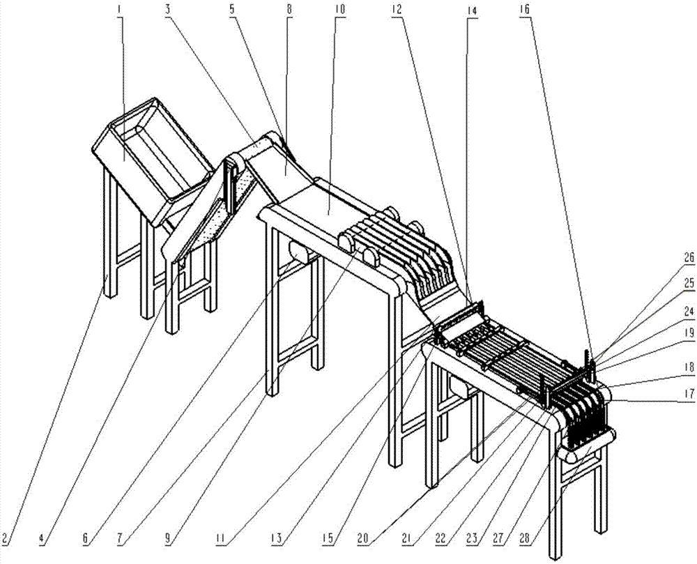
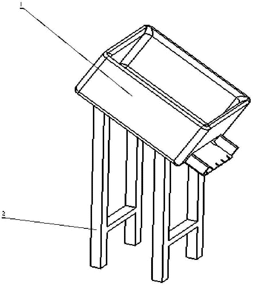
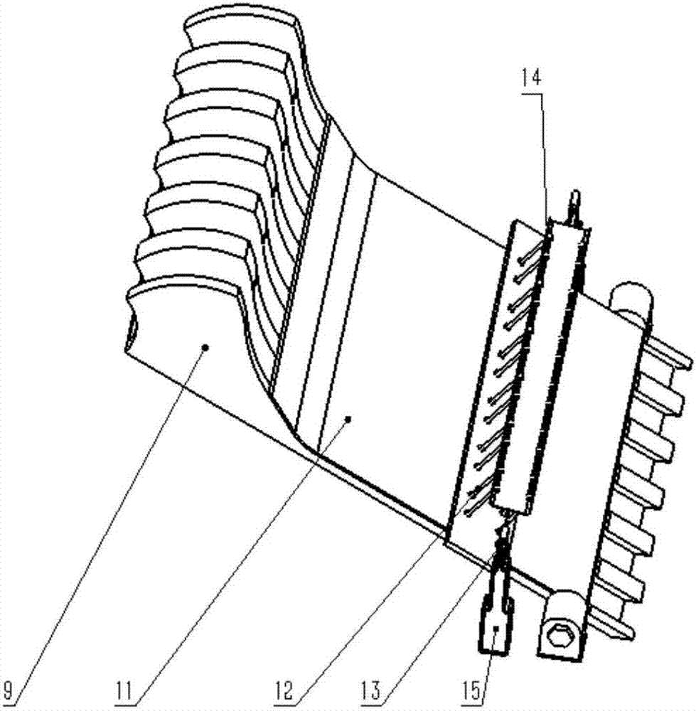
[0015] The main structure of the automatic alignment device for bearing cages involved in this embodiment includes: a hopper 1, a hopper support frame 2, a barb conveyor belt 3, a roller 4, a pulley 5, a speed regulating motor 6, a frame 7, a slide plate 8, a diverter Baffle plate 9, diverting conveyor belt 10, height-limiting slide plate 11, double-row pin 12, stepper motor 13, distance-limiting rotating shaft 14, distance-limiting support frame 15, round belt track 16, faceted conveyor belt 17, width-limiting baffle 18. Gear 19, rack 20, deceleration motor 21, height-limiting pin 22, reverse pick-up hook 23, pick-up hook support shaft 24, reverse collection rod 25, reverse collection rod support frame 26, front collection rod 27 and front collection rod Stopper 28; hopper 1 is the storage part of the bearing cage, which is fixedly connected with the hopper support frame 2 by bolts, the discharge port of hopper 1 is connected with the barb conveyor belt 3 at an angle of 90 deg...
PUM
Abstract
The invention belongs to the technical field of automatic arraying equipment, and relates to an automatic arraying device for bearing retainers. The automatic arraying device comprises a hopper, a hopper supporting frame, a barb conveying belt, a roller, a belt wheel, an adjustable-speed motor, a rack, a sliding plate, a flow dividing baffle, a flow dividing conveying belt, a height-limiting sliding plate, double-row contact pins, a stepping motor, a distance-limiting rotating shaft, a distance-limiting supporting frame, a round belt rail, a split side conveying belt, a width-limiting baffle, gears, racks, a gear motor, height-limiting stopping pins, a reverse side picking hook, a picking hook supporting shaft, a reverse side collecting rod, a reverse side collecting rod supporting frame, a front side collecting rod and a front side collecting rod stopping block; and the two sets of gears and racks which are in gear fit are installed at the positions, at the tail ends of the round belt rail, of the two sides of the rack, the picking hook supporting shaft is installed on the racks, the reverse side picking hook is used for grabbing the bearing retainers in the reverse side state, equal-distance feeding is achieved, front and reverse side automatic sorting and arraying stacking are achieved, and the automatic arraying device is scientific and reasonable in overall structural design, high in production efficiency, low in mistaken making rate and environment-friendly to the environment, and saves labor and force.
Description
Technical field: [0001] The invention belongs to the technical field of automatic arranging equipment, and relates to an automatic arranging device for bearing cages, especially a device that uses a three-stage transmission mechanism to realize equidistant feeding, automatic sorting and arranging of the front and back sides of the bearing cage, especially Automatic aligning device for deep groove ball bearing cages. Background technique: [0002] The bearing cage is one of the important parts of the bearing, which is used to support and separate the various rolling elements, especially the deep groove ball bearing cage. Due to its complex shape and irregular structure, it requires a lot of labor and labor in mass production. Time for sorting and alignment, so that the cages can be stacked or enter the next production process. Although there is an alignment machine for alignment, it is easy to accumulate cages during the alignment process, which is not convenient for alignme...
Claims
Application Information
Patent Timeline
Application Date:The date an application was filed.
Publication Date:The date a patent or application was officially published.
First Publication Date:The earliest publication date of a patent with the same application number.
Issue Date:Publication date of the patent grant document.
PCT Entry Date:The Entry date of PCT National Phase.
Estimated Expiry Date:The statutory expiry date of a patent right according to the Patent Law, and it is the longest term of protection that the patent right can achieve without the termination of the patent right due to other reasons(Term extension factor has been taken into account ).
Invalid Date:Actual expiry date is based on effective date or publication date of legal transaction data of invalid patent.