Receiver

a receiver and receiver technology, applied in the field of receivers, can solve the problem that input signals cannot be sufficiently separated from irregular impulse nois

Inactive Publication Date: 2009-07-14
KK TOSHIBA
View PDF6 Cites 6 Cited by
  • Summary
  • Abstract
  • Description
  • Claims
  • Application Information

AI Technical Summary

Benefits of technology

[0007]A receiver in accordance with another embodiment of the present invention is provided with an antenna to make a received signal out of a transmitted signal, a first local oscillator to generate a reference local oscillation signal and an orthogonal local oscillation signal phase-shifted by 90° from the reference local oscillation signal, an I / Q mixer including an I mixer and a Q mixer wherein the I mixer mixes the received signal with the reference local oscillation signal from the local oscillator and the Q mixer mixes the received signal with the orthogonal local oscillation signal from the local oscillator, a noise detector to carry out peak and differential detections of output signals from the I / Q mixer to detect impulse noises in a form of a pulse signal from the received signal, a first interpolator carrying out shaping of waveforms of the output signals from the I / Q mixer in response to the pulse signal, a demodulator connected to the first interpolator, and a second interpolator which carries out shaping of waveforms of the output signals from the demodulator in response to the pulse signal from the noise detector.

Problems solved by technology

An AM radio or AM tuner particularly installed in a car to receive amplitude-modulated electromagnetic waves through its antenna suffers impulse noise from the ignition of your own car or cars of others, tram noise from tramcars or motor noise from electrically driven cars.
Since AM input signals in particular, however, vary their amplitudes, the input signals cannot be sufficiently separated from irregular impulse noise at the detection of noise components on the basis of a reference.

Method used


Image

  • Receiver
  • Receiver
  • Receiver

Examples


first embodiment

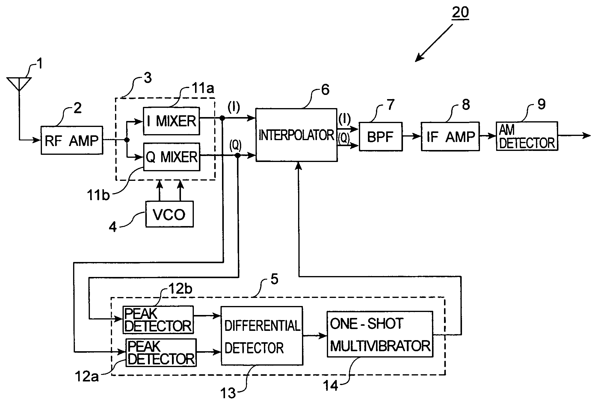
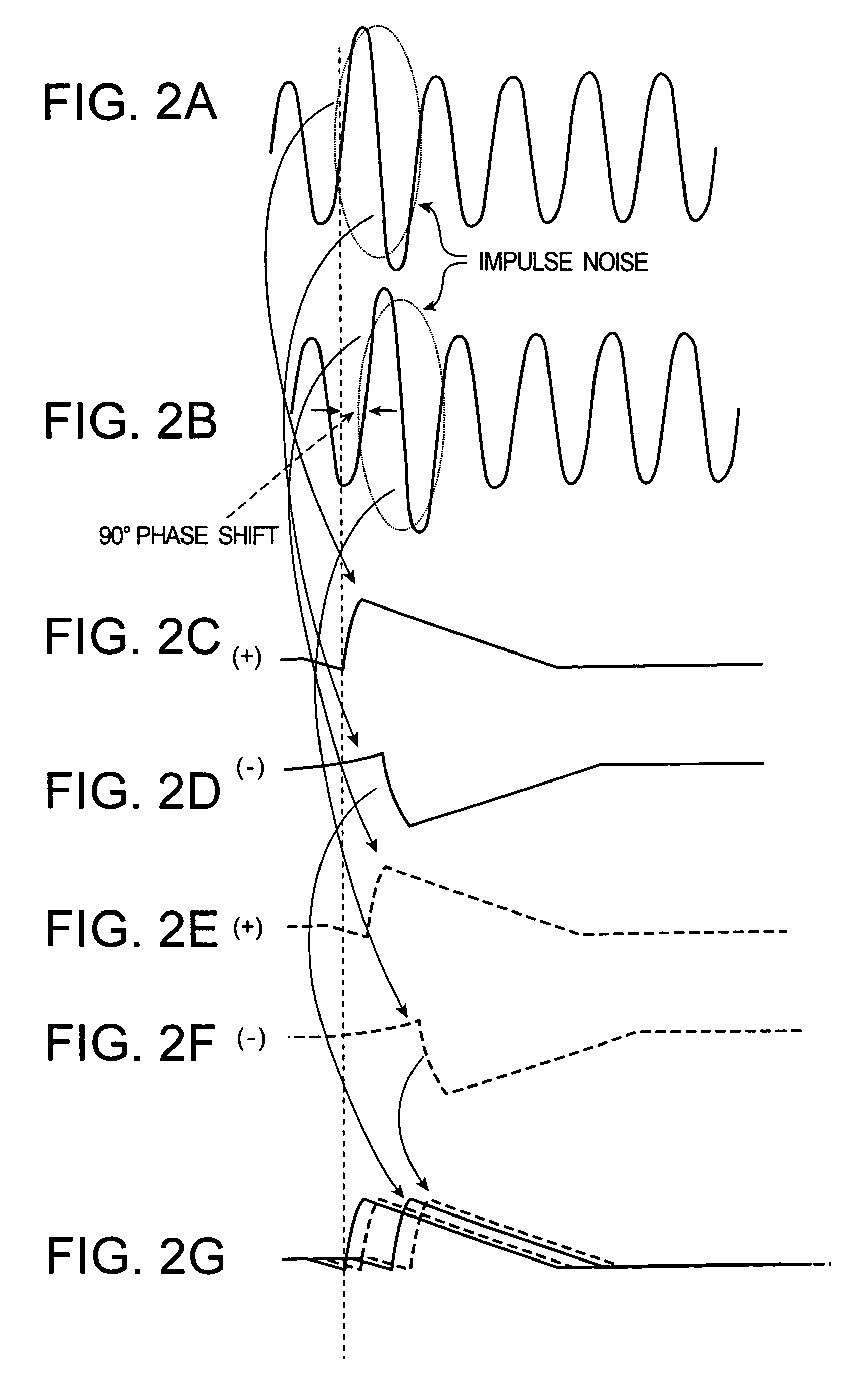
[0020]A receiver of the first embodiment in accordance with the present invention is described with reference to the drawings. FIG. 1 is a block diagram of a single heterodyne type AM receiver. In order to eliminate or reduce impulse noise, an I / Q mixer, an impulse noise detector and an interpolator are provided in the embodiment.

[0021]As shown in FIG. 1, AM receiver 20 is provided with antenna 1, RF amplifier 2, I / Q mixer 3, voltage controlled oscillator (VCO) 4, impulse noise detector 5, interpolator 6, band pass filter (BFF) 7, intermediate frequency (IF) amplifier 8 and AM detector 9. Antenna 1 receives outer electromagnetic waves (AM signals) and supplies the signal to RF amplifier 2 through a filter (not shown). RF amplifier 2 amplifies weak outer signals received through antenna 1.

[0022]VCO 4 functioning as a voltage controlled oscillator outputs a local oscillation signal, the frequency of which is different from a receiving frequency by a predetermined frequency. I / Q mixer ...

second embodiment

[0040]Now referring to FIG. 5, a receiver in accordance with the second embodiment of the present invention will be described. FIG. 5 is a block diagram of a single heterodyne type AM receiver. In this embodiment, an additional interpolator is provided on the output side of an AM detector.

[0041]Components identical or similar to those of the first embodiment use the same reference numerals so that their explanations are omitted and only different components will be described below in detail.

[0042]As shown in FIG. 5, AM receiver 20a is provided with antenna 1, RF amplifier 2, I / Q mixer 3, VCO 4, impulse noise detector 5, interpolators 6a and 6b, BPF 7, IF amplifier 8 and AM detector 9.

[0043]Interpolator 6a is supplied with output signals from I / Q mixer 3, carries out waveform-interpolations of the output signals in response to an interpolation signal output from impulse noise detector 5 and eliminates impulse noises from them. Interpolator 6b is supplied with an output signal detecte...

third embodiment

[0046]Now referring to the attached drawings, a receiver of the third embodiment will be described. FIG. 6 is a block diagram of a double super heterodyne type AM receiver. The receiver of this embodiment includes two I / Q mixers.

[0047]Components identical or similar to those of the first embodiment use the same reference numerals so that their explanations are omitted and only different components will be described below in detail.

[0048]As shown in FIG. 6, AM receiver 20b is provided with antenna 1, RF amplifier 2, I / Q mixers 3a and 3b, VCO 4, impulse noise detector 5, interpolator 6, BPF 7, IF amplifier 8, AM detector 9 and oscillator (OSC) 15. Here, since the structure of I / Q mixers 3a and 3b is in two stages, characteristics of output signals supplied from I / Q mixers 3a and 3b to interpolator 6 are improved, so that loads for latter stages than I / Q mixers 3a and 3b, such as interpolator 6, are reduced. Here, since I / Q mixers 3a and 3b are two stages, a load of a later stage than ...


PUM


Abstract

AM receiver 20 is provided with antenna 1, RF amplifier 2, I / Q mixer 3, VCO 4, impulse noise detector 5, interpolator 6, BPF 7, IF amplifier 8 and AM detector 9. I / Q mixer 3 is composed of I mixer 11a as an in-phase mixer and Q mixer 11b as an orthogonal mixer. Impulse noise detector 5 generates an interpolation signal from in-phase and orthogonal output signals from I / Q mixer 3. Interpolator 6 carries out shaping of waveforms of the output signals from I / Q mixer 3 in response to the interpolation signal and eliminates impulse noises from the output signals from I / Q mixer 3.

Description

CROSS-REFERENCE OF RELATED APPLICATIONS[0001]This application is based upon and claims the benefit of priority from the prior Japanese Patent Application No. 2004-365788, filed on Dec. 17, 2004, the entire contents of which are incorporated herein by reference.FIELD OF THE INVENTION[0002]This invention generally relates to a receiver and, more particularly, to an AM or FM receiver used for a radio, tuner, or the like.BACKGROUND OF THE INVENTION[0003]An AM radio or AM tuner particularly installed in a car to receive amplitude-modulated electromagnetic waves through its antenna suffers impulse noise from the ignition of your own car or cars of others, tram noise from tramcars or motor noise from electrically driven cars. In order to reduce such impulse noise components, a noise canceller is conventionally often used (see Japanese Unexamined Patent Publication No. 2000-10463). The noise canceller is provided with an automatic gain control (AGC) circuit which compensates fluctuations in...

Claims


Application Information

Patent Timeline
Patent Type & Authority Patents(United States)
IPC IPC(8): H04B1/18
CPCH04B1/10
Inventor MATSUMOTO, YUTAKA
Owner KK TOSHIBA
Why Eureka
Try Eureka