
System comprised of a chip catcher and a safety guard for a power tool

a safety guard and chip catcher technology, which is applied in the field of chip catcher and a safety guard system for power tools, can solve the problems of only being able to attach dust bags or vacuum hoses, unable to remove chips or vacuum hoses, and inconvenient for users to remove them, so as to reduce the size of the safety guard, minimize the influence of interfering moments during the operation of hand-guided power tools, and easily and conveniently maneuver the power tools

Active Publication Date: 2009-07-21
ROBERT BOSCH GMBH
View PDF19 Cites 10 Cited by
  • Summary
  • Abstract
  • Description
  • Claims
  • Application Information

AI Technical Summary

Benefits of technology

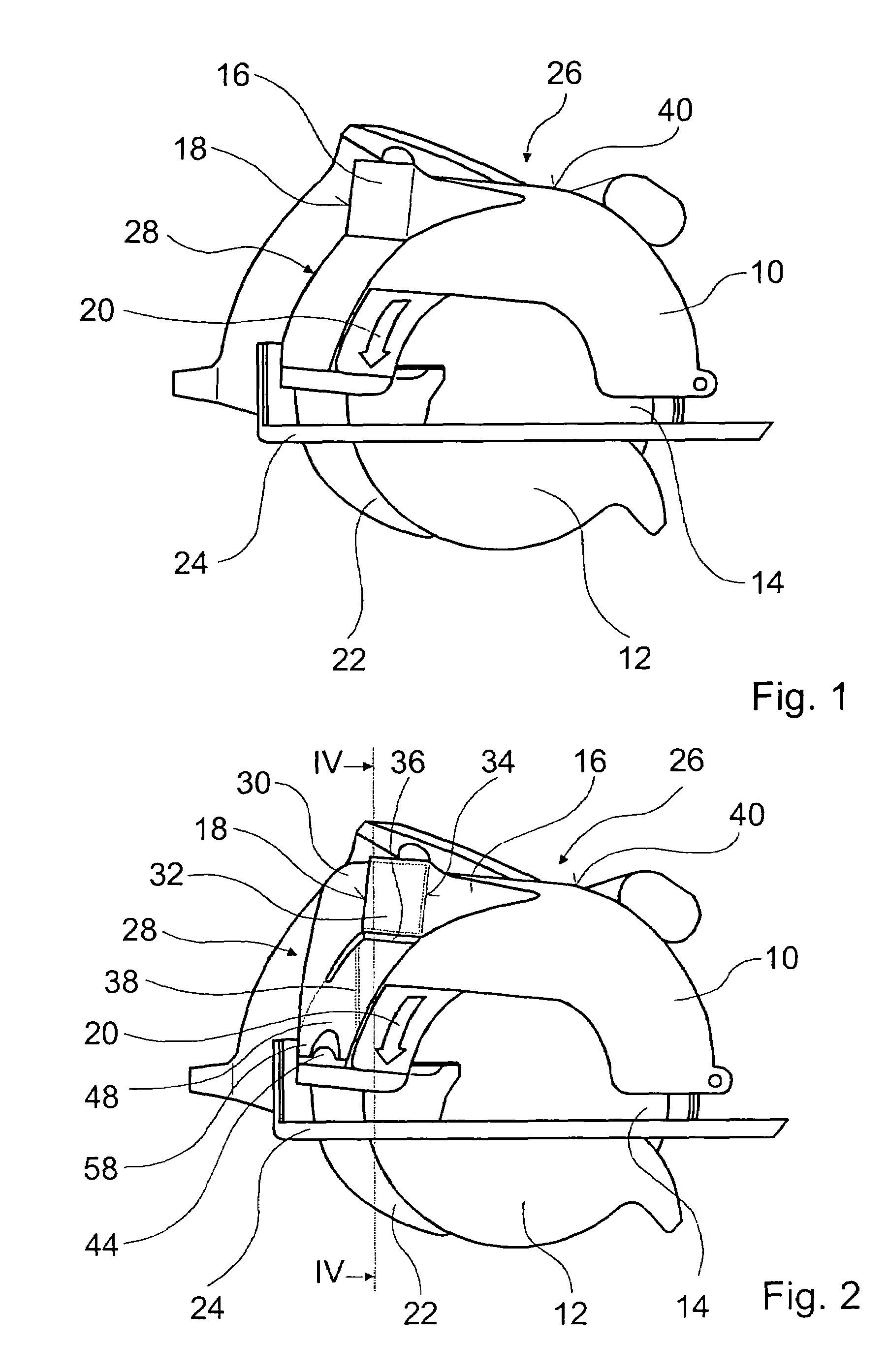
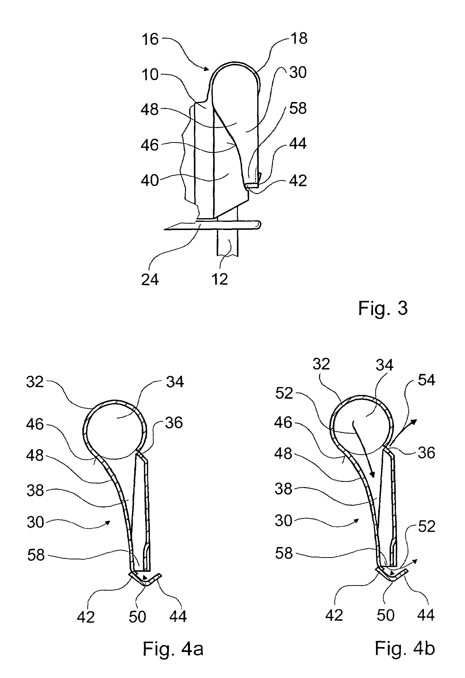
[0009]According to the invention, the housing contains an air outlet spatially separate from a chip-collecting region for chips. The chip-collecting region carries away the purified air while the chips remain behind in the chip catcher and can either be collected there and removed later or can be ejected at an intentionally low speed next to the hand-guided circular saw. This can also occur at intervals without having to interrupt the work. In order to remove chips collected in the chip catcher, the chip catcher can also be removed from the power tool or its safety guard and conveniently emptied.
[0018]If chips can be ejected at a low speed next to the power tool when the flap is open, then the chips can be conveyed outside with the least possible inconvenience to the user. When the flap is in the open state, it preferably serves as a chip chute and / or as an extension of a chip chute. This avoids an unnecessary agitation of the ejected chips.

Problems solved by technology

In some cases, ejected chips or a vacuum hose prove inconvenient to a user.
In so doing, interfering moments of the vacuum hose can impinge on the saw blade.
A dust bag or vacuum hose can only be attached by means of an adapter, which hinders the function of passive chip catching devices by slowing down the chips.
It is problematic that work must always be carried out with the box in place since it is an integral component of the safety guard.
A chip bag is in fact removable, but has the disadvantage that the porous envelope material constitutes an air resistance so that only part of the chip-laden air flows into the chip bag while a significant portion of the chips escape to the outside through other openings in the safety guard.

Method used


Image

  • System comprised of a chip catcher and a safety guard for a power tool
  • System comprised of a chip catcher and a safety guard for a power tool
  • System comprised of a chip catcher and a safety guard for a power tool

Examples


Embodiment Construction

[0026]Parts that remain essentially the same have been provided with the same basic reference numerals in the drawings.

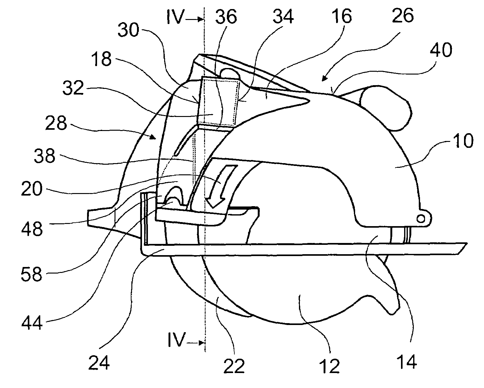
[0027]FIG. 1 shows a side view of a power tool 26 embodied in the form of a preferred hand-guided circular saw, without a chip catcher. A saw blade 14 is covered to a large degree by a movable pivoting lower guard 12 and a stationary safety guard 10. The safety guard 10 has a cover contour 28. A baseplate 24 serves to guide the power tool 26 over a work piece to be machined. During sawing, chips inside the safety guard 10 are transported in the rotation direction 20 of the saw blade 14 and exit the safety guard 10 via a chip ejector 16 through an opening 18. The chip ejector 16 is situated on the circumference of the safety guard 10 and is designed so that either a chip catcher or a vacuum close can be fastened to it; preferably the chip ejector 16 is embodied as round and conical. In addition, a conventional rip fence 22 is provided; the present invention can also ...


PUM

PropertyMeasurementUnit
circumferenceaaaaaaaaaa
speedaaaaaaaaaa
air resistanceaaaaaaaaaa

Abstract

A system is comprised of a chip catcher and a safety guard for a power tool that generates chips, in particular a hand-guided power tool, having an inlet region for admitting a flow of air containing a chip / air mixture and for detachably connecting a chip ejector and having an inlet region for admitting a flow of air containing a chip / air mixture and for detachably connecting to a chip ejector and having an encompassing housing that is provided for attachment to the safety guard. The housing contains an air outlet spatially separate from a chip-collecting region for chips.

Description

CROSS-REFERENCE TO A RELATED APPLICATION[0001]The invention described and claimed hereinbelow is also described in German Patent Application DE 10 2004 003.6 filed on Jan. 27, 2004. This German Patent Application provides the basis for a claim of priority of invention under 35 U.S.C. 119(a)-(d).BACKGROUND OF THE INVENTION[0002]The invention is based on a chip catcher and a system comprised of a chip catcher and a safety guard for a power tool, in particular a hand-guided power tool.[0003]When working with hand-guided circular saws and similar power tools such as planers, routers, and the like, large quantities of chips are produced that are conveyed from a safety guard to the outside, either directly or indirectly, by means of a chip ejector, are sucked away by a vacuum connection, or are captured in a chip bag. Typically, a round chip ejector is provided on the side of the safety guard so that the chips are ejected out the side of the power tool. In some cases, ejected chips or a v...

Claims


Application Information

Patent Timeline
Patent Type & Authority Patents(United States)
IPC IPC(8): B27B9/00B23Q11/00B27G3/00B23D59/00
CPCB23Q11/005B23D59/006
Inventor ROEHM, HEIKOWEBER, STEFFEN
Owner ROBERT BOSCH GMBH
Learn More