Lower limit adjustment mechanism for riding type mower

a technology of lower limit adjustment and riding mower, which is applied in the direction of mowers, agricultural tools and machines, etc., can solve the problems of difficult operation of lower limit adjustment elements, difficult to perform lower limit adjustment of moving devices, and difficult to set the limit of swinging motion of drive arms, etc., to achieve the effect of easy to achieve lower limit adjustment of mower units

Active Publication Date: 2009-07-21
KUBOTA CORP
View PDF13 Cites 3 Cited by
  • Summary
  • Abstract
  • Description
  • Claims
  • Application Information

AI Technical Summary

Benefits of technology

[0008]It is an object of the present invention to provide a riding type mower allowing lower limit adjustment of a mower unit to be easily accomplished regardless of a position of a stopper.

Problems solved by technology

Further, the configuration thereof is such that a stopper acts on a restraint pin provided in a drive arm of the elevation link mechanism, setting the limit of a swinging motion of the drive arm.
When employing the above-described conventional technology, since an adjustment knob constituting a lower limit adjustment element for adjusting the stopper through rotation thereof is linked to the stopper such that the adjustment knob is rotated about an axis of rotation identical to an axis of rotation of the stopper, if the stopper is, for example, disposed so as to act on the linking mechanism of the mower unit and the operation mechanism, the lower limit adjustment element must be disposed below the driving seat, and therefore, the lower limit adjustment element becomes difficult to operate and lower limit adjustment of the moving device becomes difficult to perform.

Method used


Image

  • Lower limit adjustment mechanism for riding type mower
  • Lower limit adjustment mechanism for riding type mower
  • Lower limit adjustment mechanism for riding type mower

Examples


Embodiment Construction

[0025]The following is a description of embodiments of the present invention, with reference to the accompanying drawings.

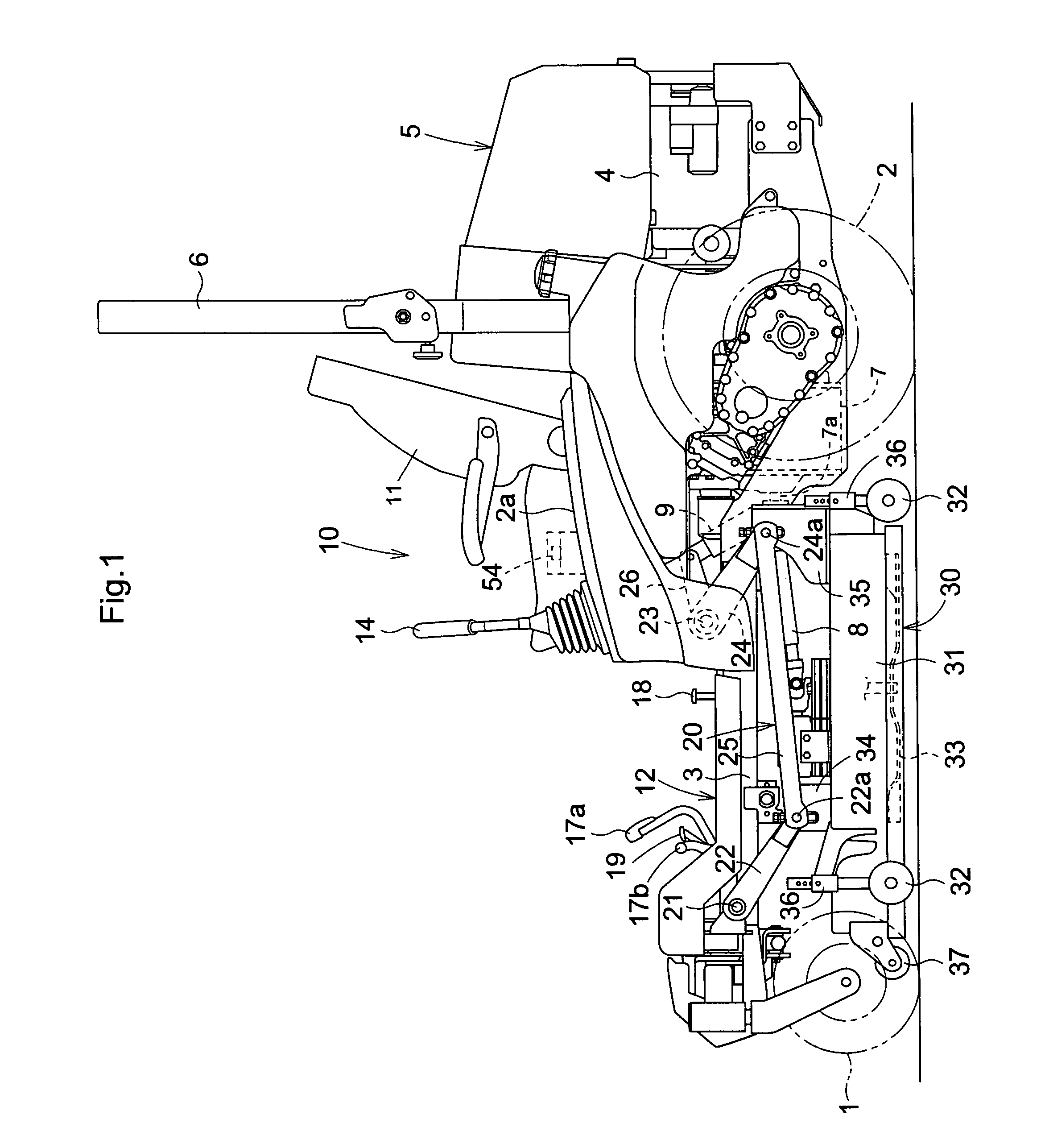
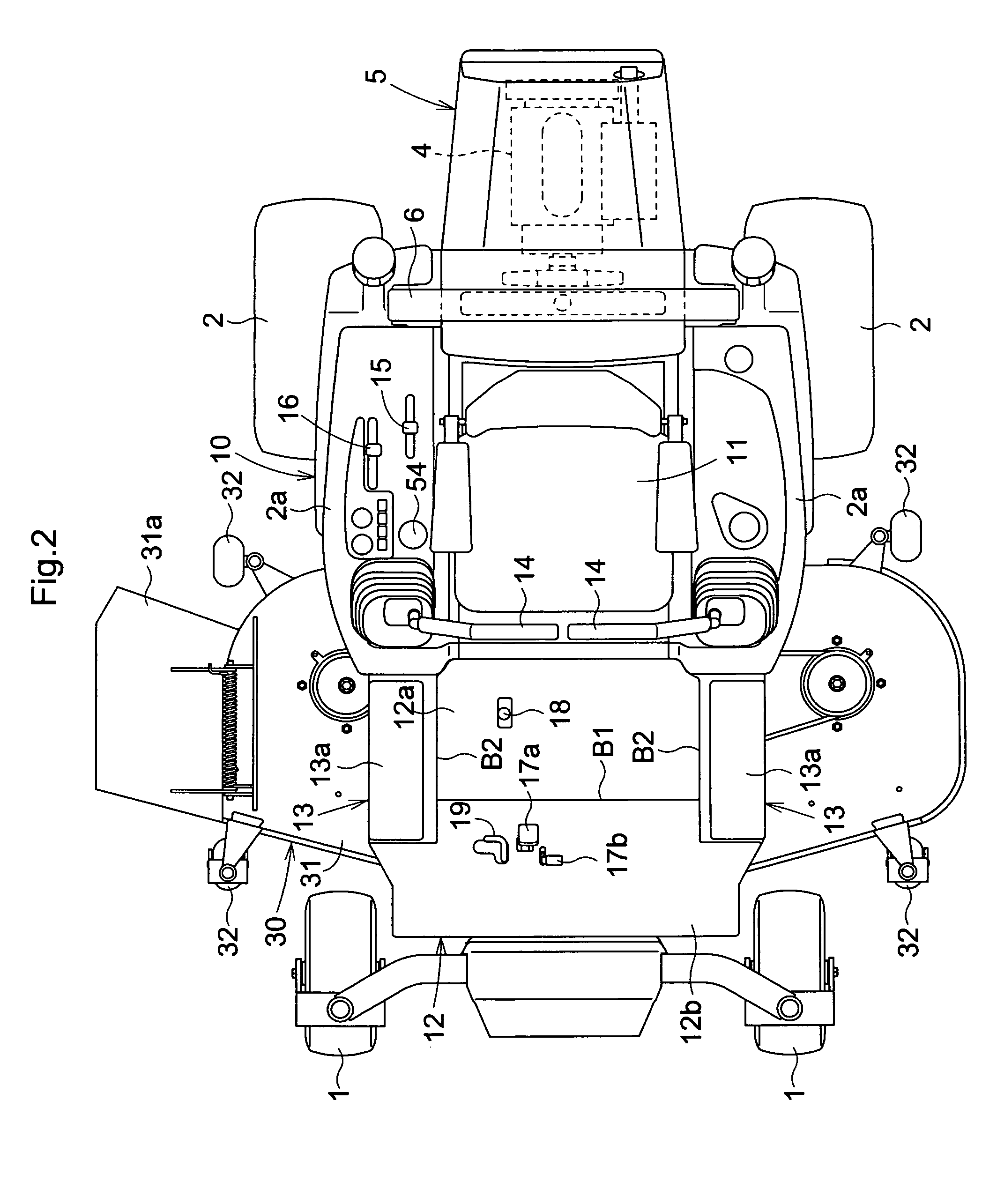
[0026]As shown in FIG. 1 and FIG. 2, a riding type mower has a frame 3 of a self-propelled chassis providing a pair of caster type front wheels 1 disposed left and right in such a manner as to be capable of freely rotating, a pair of rear wheels 2 disposed left and right in such a manner as to be capable of being freely driven, a drive section 5 wherein an engine 4 provided at a rear-end section of the frame 3 is installed, a riding driving section 10 wherein a driving seat 11 disposed close to a front side of the drive section 5 is installed, and a topple protection frame 6 disposed close to a rear side of the driving seat; and is configured such that the frame 3 is connected with a mower unit 30 through an action of a link mechanism 20 disposed between the front and rear wheels of the frame 3, and an output of the engine 4 is transferred to the mower unit 30 fr...


PUM


Abstract

A riding type mower comprises: a plurality of wheels including at least one driven wheel; a vehicle body supported by the plurality of wheels; a driver's seat supported by the vehicle body; a mower unit located below the vehicle body; a suspension mechanism for vertically movably supporting the mower unit from the vehicle body, the suspension mechanism having a restraint member operatively connected to the suspension mechanism; an operation mechanism for operating the suspension mechanism; a stopper for setting a lower limit for a vertical position of the mower unit to define a cutting height by abutment against the restraint member, the stopper is adapted to be rotated to change the lower limit; a lower limit adjustment element located laterally of the driver's seat and rotatable to rotate the stopper; and a linking mechanism for operatively connecting the lower limit adjustment element with the stopper.

Description

BACKGROUND OF THE INVENTION[0001]1. Field of the Invention[0002]The present invention relates to riding type mowers having a mower unit connected to the chassis thereof in such a manner as to be capable of freely moving upwards and downwards.[0003]2. Description of Related Art[0004]In conventional riding type mowers, a mower unit is moved downwards when an operation mechanism is operated, and when the moving device has moved downwards to a set height, a stopper acts, and downward motion of the mower unit stops. In this way, by simply operating the operation mechanism to a downward-movement side, conventional riding type mowers can accurately move a mower unit downward to a desired height set by a stopper.[0005]This type of riding type mower is presented, for example, in JP 2002-238325A (paragraphs 0033 and 0034; FIG. 2, FIG. 4, and FIG. 6).[0006]The mower disclosed therein is configured such that a hydraulic cylinder (equivalent to an operation mechanism) is linked to a mower consti...

Claims


Application Information

Patent Timeline
Patent Type & Authority Patents(United States)
IPC IPC(8): A01D34/00
CPCA01D34/74A01D34/64A01D34/661
Inventor KOMORIDA, TAKESHIUMEMOTO, HIDEYAESAKI, YOSHIYUKI
Owner KUBOTA CORP
Why Eureka
Try Eureka