
Instrument for direct laryngoscopy with a rigid blade and flexible fiberoptics

a technology of laryngoscope and flexible fiberoptics, applied in the field of medical instruments, can solve the problems of state of prior art technology, difficulty in intubation, and difficulty in actual passage of endotracheal tubes between vocal cords,

Active Publication Date: 2009-07-21
GARDNER IP HLDG LLC
View PDF17 Cites 26 Cited by
  • Summary
  • Abstract
  • Description
  • Claims
  • Application Information

AI Technical Summary

Benefits of technology

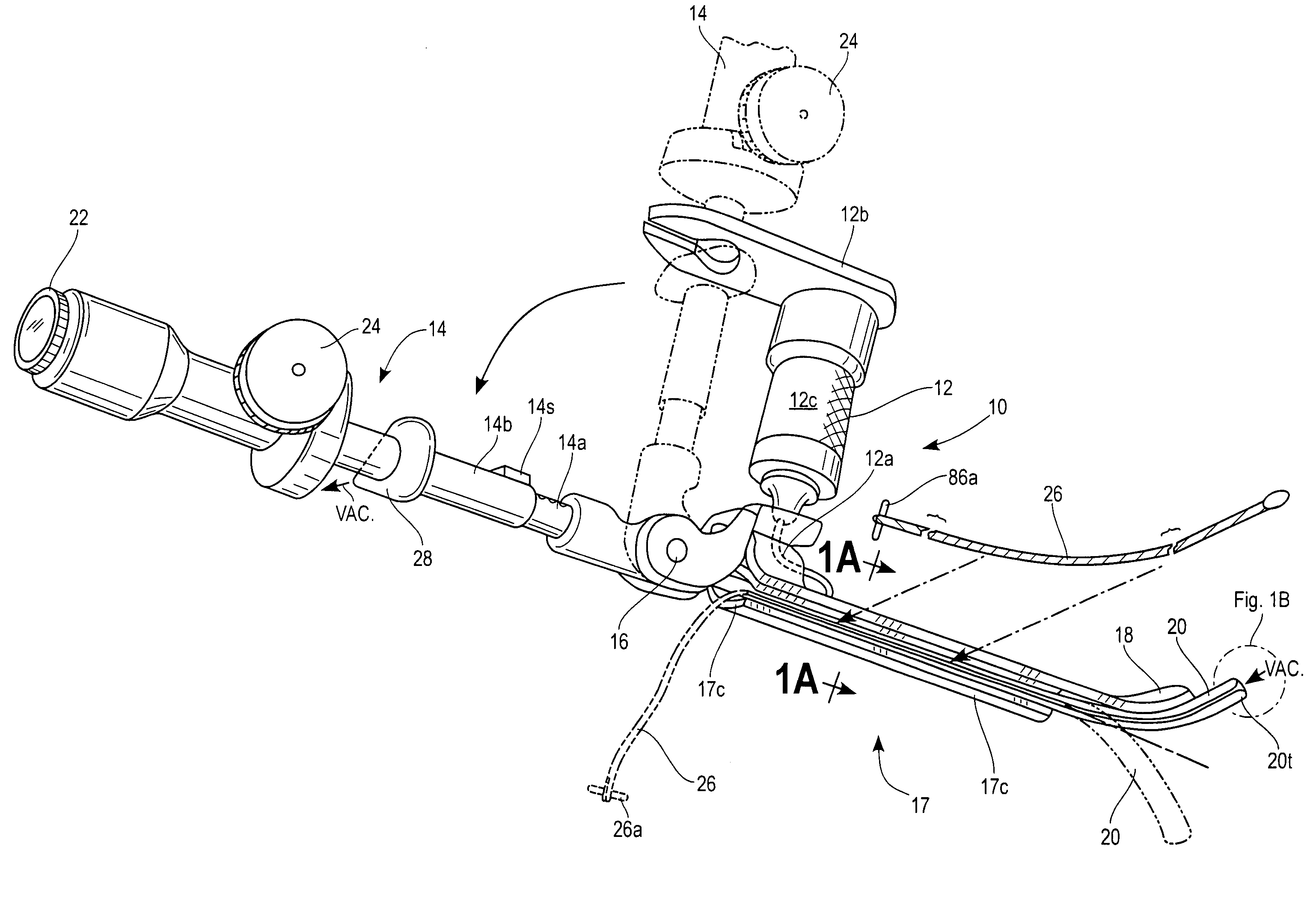
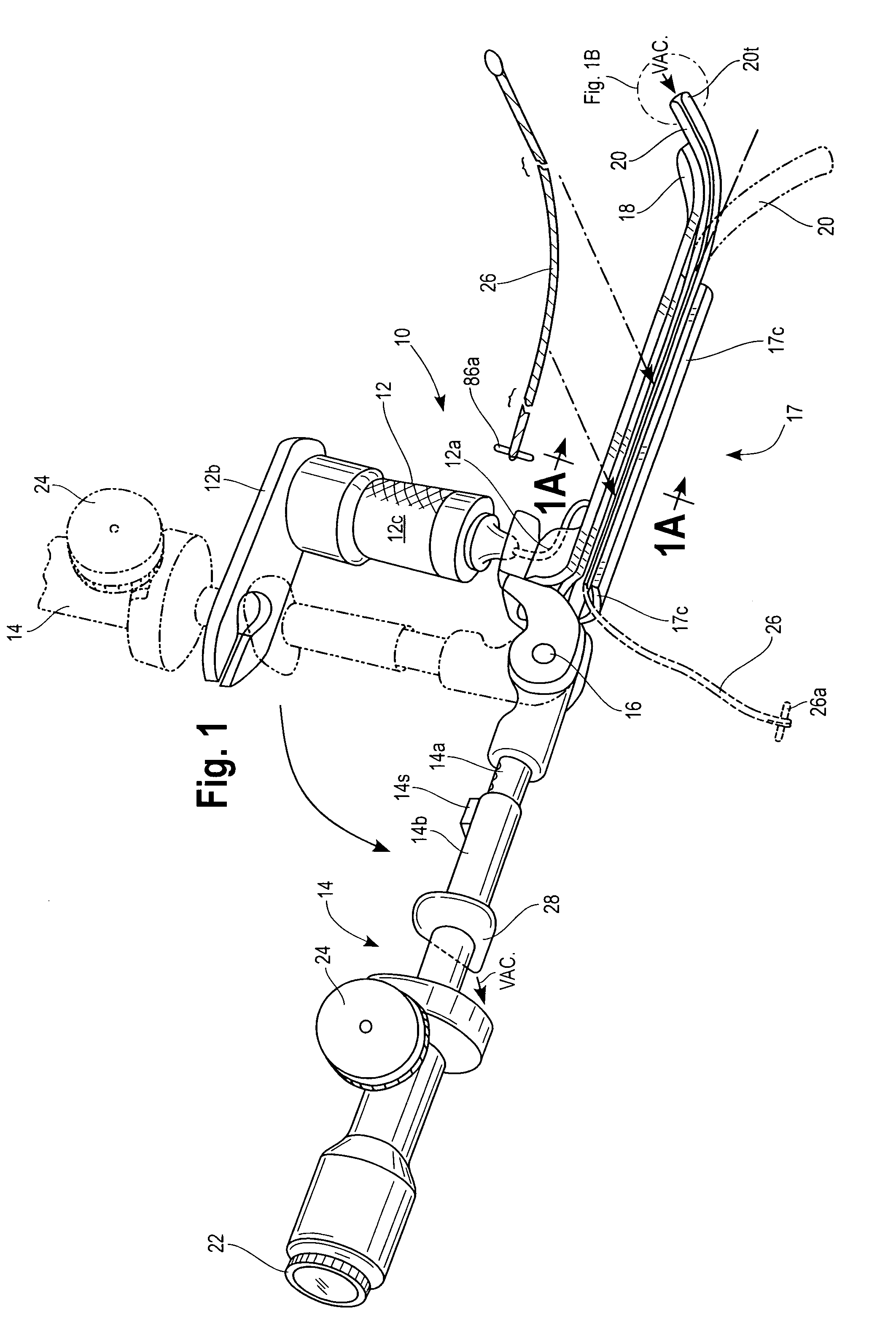
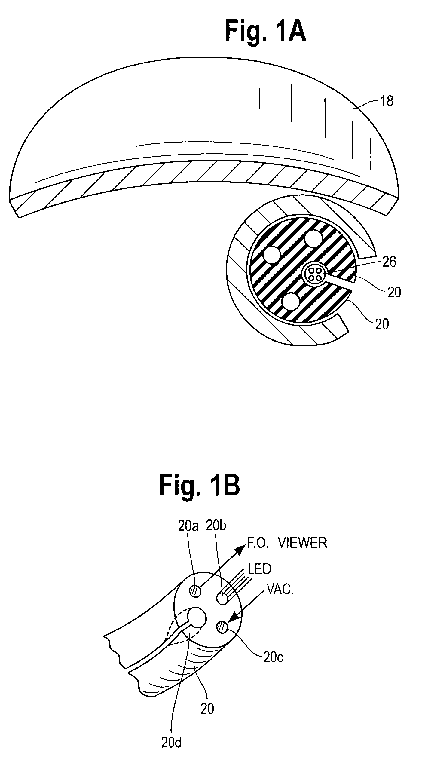
[0009]In one preferred embodiment of the device of the present invention, the handle and viewing device are rotationally attached together for storage and also to provide novel angles, between the handle and viewer, to assist in direct viewing of the patient's larynx upon the initial insertion of the instrument into the patient's oropharynx. In several embodiments of the device of the present invention, the viewing member comprises an extension tube attached to the rigid blade, in which a flexible tube member is maintained, and a lens or monitor connection defined at its proximal end, operationally connected to the flexible tube. The extension tube of the viewing member is provided with means for telescopically extending, and subsequently retracting the member, so as to assist the user in viewing the patient's anatomy through the lens and flexible tube, by permitting closer inspection within the patient's larynx. The extended or retracted position of the flexible tube can be secured with a clip or other available means.

Problems solved by technology

It is generally agreed that laryngoscopy of many patients, with the state of prior art technology is at times difficult, concomitantly making intubation difficult.
In addition, once visualization of the vocal cords is accomplished, actual passage of an endotracheal tube between the vocal cords with state of prior art may also be difficult.

Method used


Image

  • Instrument for direct laryngoscopy with a rigid blade and flexible fiberoptics
  • Instrument for direct laryngoscopy with a rigid blade and flexible fiberoptics
  • Instrument for direct laryngoscopy with a rigid blade and flexible fiberoptics

Examples


Embodiment Construction

[0031]While the present invention is susceptible of embodiment in various forms, there is shown in the drawings a number of presently preferred embodiments that are discussed in greater detail hereafter. It should be understood that the present disclosure is to be considered as an exemplification of the present invention, and is not intended to limit the invention to the specific embodiments illustrated. It should be further understood that the title of this section of this application (“Detailed Description of the Illustrative Embodiment”) relates to a requirement of the United States Patent Office, and should not be found to limit the subject matter disclosed herein.

[0032]Referring to the figures, a laryngeal device or laryngoscope 10 having a handle 12 and a viewing member 14 is provided. Viewing member 14, in a preferred embodiment is made so that it can telescope between a first extended position 14a (FIG. 4A) and a second contracted position 14b (FIG. 4B). Telescoping portion ...


PUM


Abstract

A laryngoscope and flexible viewing device having means to carry an endotracheal tube into a patient and method of using the device are provided. The device allows a single user to view the interior of a patient's anatomy and change the view to better determine the path for intubation. The device can be used by a single individual to simultaneously open the pathway to a patient's trachea and then deliver an intubation device, such as an endotracheal tube, without the assistance of another person. The device provides several options for the practitioner to both visualize the patient's larynx and deliver an endotracheal tube into the trachea, especially in patients considered to have difficult anatomy to intubate. The viewing device in a preferred embodiment is a fiberoptic scope and the device includes a pivoting means to allow the viewing means to provide a more panoramic view of the patient's throat area.

Description

[0001]The present application claims the priority of U.S. Provisional Patent application No. 60 / 676,387, filed on Apr. 29, 2005, and incorporates that application herein as if set forth in its entirety.FIELD OF THE INVENTION[0002]The present invention concerns a medical instrument that allows for both direct laryngoscopy with a rigid blade and indirect flexible fiberoptics in the same instrument. More particularly the present invention concerns a laryngoscope having a rigid blade to retract oropharyngeal tissue and a flexible fiberoptic scope with guidewire systems, to permit examination of the larynx during laryngoscopy of a patient as well as a means to intubate a patient.BACKGROUND OF THE INVENTION[0003]The intubation of a patient in need of medical care is a frequent occurrence in operating theaters, emergency rooms and other medical situations. The insertion of a tube, through which life saving and sustaining oxygen may be provided, must be made through the natural defenses pro...

Claims


Application Information

Patent Timeline
Patent Type & Authority Patents(United States)
IPC IPC(8): A61B1/267
CPCA61B1/012A61B1/01A61B1/267
Inventor GARDNER, GLENN P.
Owner GARDNER IP HLDG LLC
Learn More