Stent having an ultrasonic emitter

a technology of ultrasonic emitter and stent, which is applied in the field of stents having ultrasonic emitters, can solve the problems of symptomatic problems, possible problems of restenosis, and inability to fully address the problem of restenosis,

Active Publication Date: 2009-07-21
ALFRED E MANN FOUND FOR SCI RES
View PDF18 Cites 10 Cited by
  • Summary
  • Abstract
  • Description
  • Claims
  • Application Information

AI Technical Summary

Benefits of technology

[0005]In accordance with the present invention, a preferred system for preventing restenosis following placement in a blood vessel of a patient is comprised of (1) an expandable wire mesh tube comprised of a plurality of integral lattice portions and configured for expansion within a blood vessel of a patient, and (2) an electrically-powered biocompatible device positioned as at least one of the integral lattice portions which is comprised of (a) a controller within the biocompatible device responsive to an externally-provided command signal, and (b) an ultrasonic emitter within said biocompatible device coupled to the controller for emitting an ultrasonic wave to induce mechanical vibrations in said wire mesh to thereby minimize forming of plaque on the stent.

Problems solved by technology

Blockage of one or more of the arteries providing blood flow to the heart muscle of a patient can cause serious problems, ranging from symptomatic problems, e.g., chest pain, to heart attacks, and potentially death.
Unfortunately, restenosis may also be a problem with stents.
While such technologies are reported to be helpful, it is not believed that the problem of restenosis has been fully addressed.
Furthermore, there are a finite number of times that a scaffolding procedure may be performed, leaving the patient with little or no remaining options.

Method used


Image

  • Stent having an ultrasonic emitter
  • Stent having an ultrasonic emitter
  • Stent having an ultrasonic emitter

Examples


Embodiment Construction

[0021]The following description is of the best mode presently contemplated for carrying out the invention. This description is not to be taken in a limiting sense, but is made merely for the purpose of describing the general principles of the invention. The scope of the invention should be determined with reference to the claims.

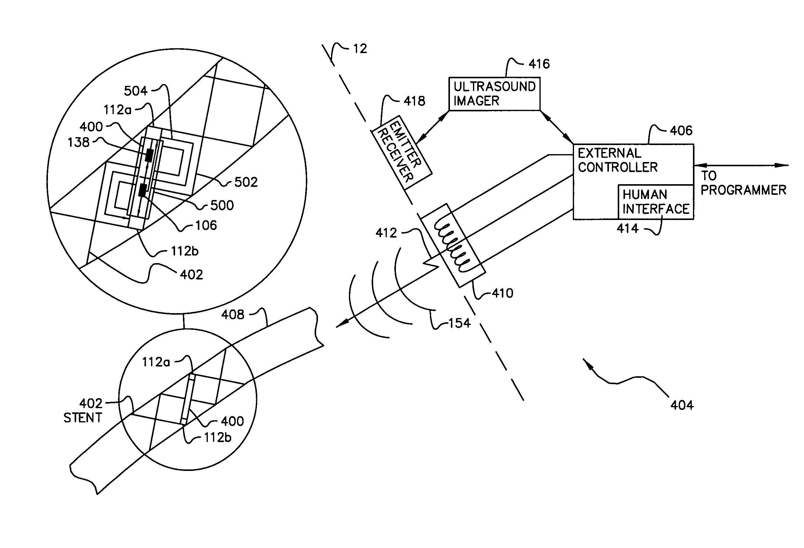
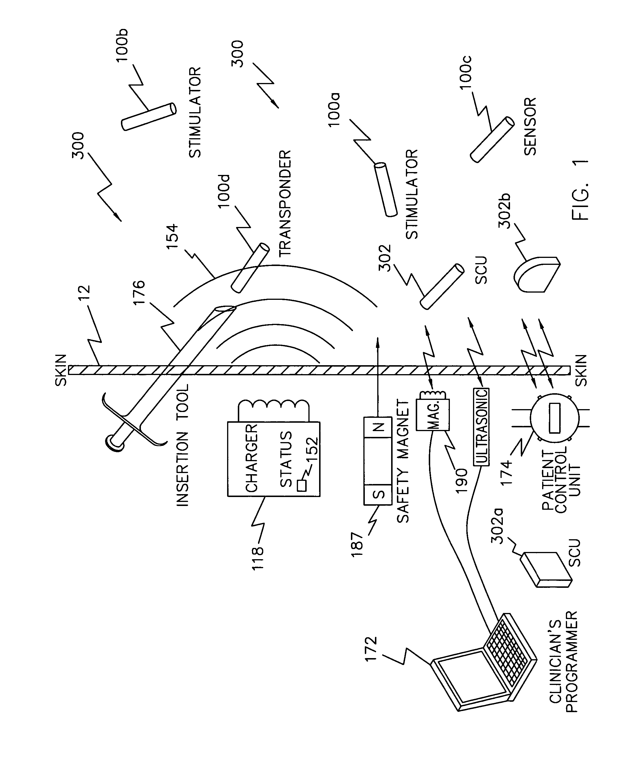
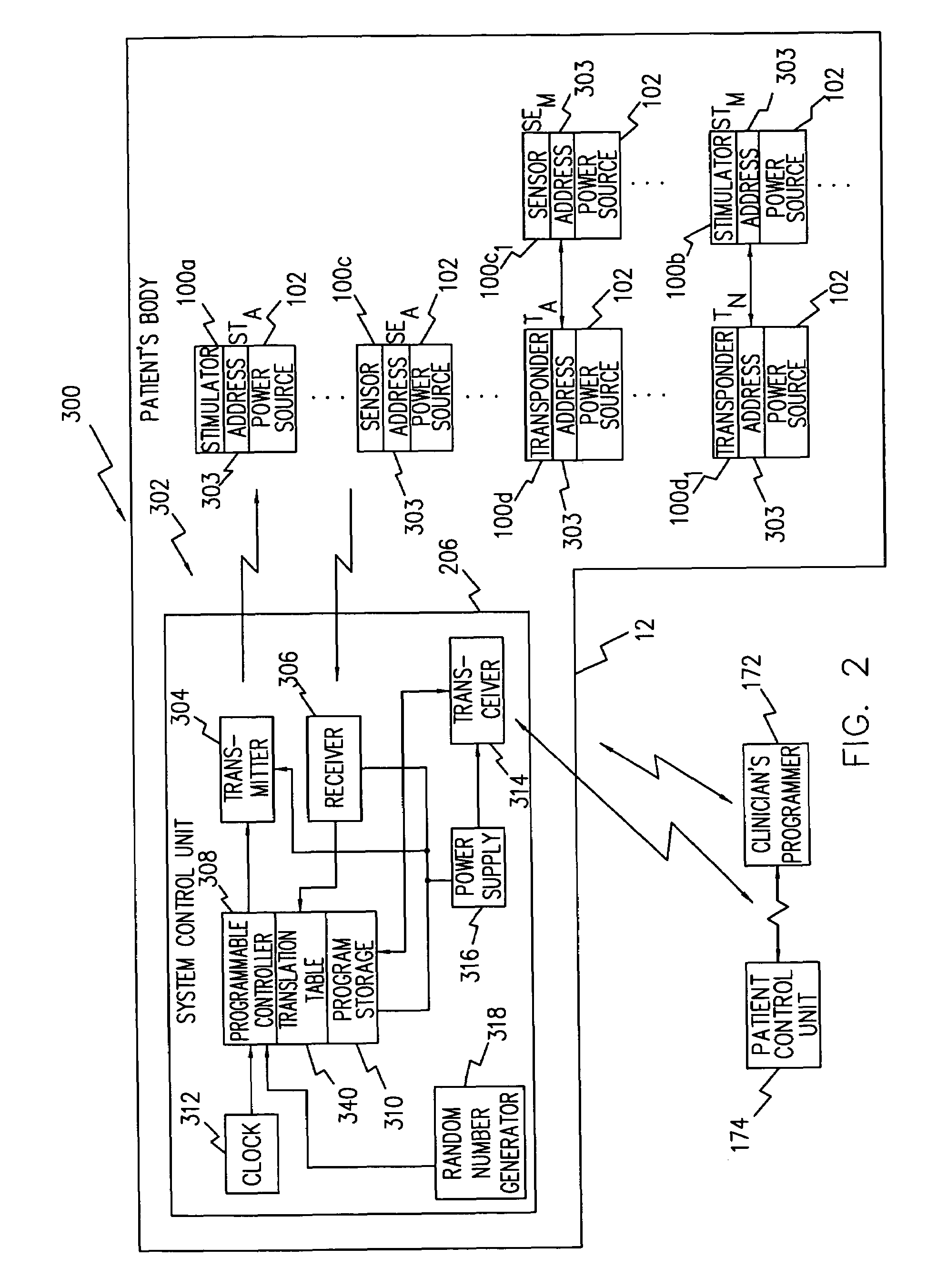
[0022]The present invention is generally directed to systems and methods for preventing restenosis following a stent procedure by using an electrically-controlled biocompatible device under control of an externally-positioned control device that issues commands to the implanted device to use an electrically controlled signal to minimize plaque accumulation on the stent. More particularly, such systems are characterized by one or more devices that are integral structural portions of the stent and are RF or battery powered. Such a device may be configured to emit an ultrasonic wave at a determined frequency corresponding to the mechanical resonance of the sten...


PUM


Abstract

A system and method that minimizes plaque accumulation on a stent and thereby restenosis that could require a subsequent invasive medical procedure following stent implantation. The stent, essentially an expandable wire mesh tube comprised of a plurality of integral lattice portions, configured for expansion within a blood vessel of a patient, is formed with an electrically-controlled, biocompatible device as one of its integral lattice portions. In a first implementation, the biocompatible device is under control of an externally-positioned controller which causes the device to emit an ultrasonic wave at a frequency corresponding to the mechanical resonance of the stent and thereby minimize accumulation of plaque. In a second or supplemental implementation, the device is or other portions of the stent are coated with a drug that can be controllably eluted by passing a current through the coating under control of the biocompatible device and the externally-positioned controller.

Description

FIELD OF THE INVENTION[0001]The present invention is generally directed to systems and methods for preventing restenosis following a stent procedure by using an electrically-powered, biocompatible device formed as an integral portion of the stent where the electrically-powered biocompatible device is under control of an externally-positioned control device that issues commands to the integral biocompatible device to use an electrically controlled signal to minimize plaque accumulation on the stent.BACKGROUND OF THE INVENTION[0002]Blockage of one or more of the arteries providing blood flow to the heart muscle of a patient can cause serious problems, ranging from symptomatic problems, e.g., chest pain, to heart attacks, and potentially death. In the most serious cases, the blocked arteries are bypassed using coronary artery bypass graft surgery (CABG) to enhance the blood flow to the sections of the heart at risk due to the restricted blood flow. While this is a relatively common pro...

Claims


Application Information

Patent Timeline
Patent Type & Authority Patents(United States)
IPC IPC(8): A61F2/06A61F2/86
CPCA61F2/86A61B17/22012A61F2250/0001A61B2017/22002
Inventor LASATER, BRIAN J.
Owner ALFRED E MANN FOUND FOR SCI RES
Why Eureka
Try Eureka