Artificial intervertebral disc utilizing a ball joint coupling

a technology of artificial intervertebral discs and couplings, which is applied in the field of spinal implant assemblies, can solve the problems of collateral injury to the patient's spine, restrict the overall flexibility of the spinal column, and restrict the normal motion of the patient, so as to eliminate the capacity for this deflection and withstand tension loads

Inactive Publication Date: 2009-07-21
HOWMEDICA OSTEONICS CORP
View PDF57 Cites 22 Cited by
  • Summary
  • Abstract
  • Description
  • Claims
  • Application Information

AI Technical Summary

Benefits of technology

[0020]To enhance the securing of the plate members to the vertebral bones, each plate member further comprises at least a lateral ring of porous coating (which may be a sprayed deposition layer, or an adhesive applied beaded metal layer, or other suitable porous coatings known in the art). This porous ring permits the long-term ingrowth of vertebral bone into the plate member, thus permanently securing the prosthesis within the intervertebral space. It shall be understood that this porous layer may extend beneath the domed metal mesh as well, but is more importantly applied to the lateral rim of the exterior surface of the plate member that seats directly against the vertebral body.
[0021]The spring mechanism disposed between the plate members provides a strong restoring force when a compressive load is applied to the plates, and also permits rotation and angulation of the two plates relative to one another. While a wide variety of embodiments are contemplated, a preferred embodiment of the spring mechanism includes a belleville washer utilized as the restoring force providing element, the belleville washer being spirally slotted and having radially extending grooves. In general, the belleville washer is one of the strongest configurations for a spring, and is highly suitable for use as a restoring force providing subassembly for use in an intervertebral spacer element which must endure considerable cyclical loading in an active human adult.
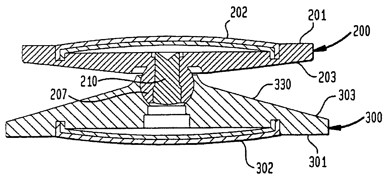
[0024]To dispose the spring mechanism between the plate members, the plate members of the artificial intervertebral disc comprise features suitable for this purpose. The spirally slotted and radially grooved belleville washer is utilized in conjunction with a ball-shaped protuberance on which it is free to rotate through a range of angles (thus permitting the plate members to rotate relative to one another through a corresponding range of angles). More particularly, one of the plate members has a circular recess on its interior surface, for housing the wide end of the belleville washer and allowing it to expand in unrestricted fashion when the belleville washer is compressed. The other of the plates has the ball-shaped protuberance on its interior surface, for rotatably holding the narrow end of the belleville washer. The protuberance has a central axial bore that receives a rivet (or a set screw, if the bore is threaded). Prior to the insertion of the rivet, the ball-shaped protuberance can deflect radially inward (so that the ball-shaped protuberance contracts). The insertion of the rivet eliminates the capacity for this deflection. The belleville washer is mounted to this ball-shaped knob in such a way that it may rotate freely through a range of angles equivalent to the fraction of normal human spine rotation (to mimic normal disc rotation). The belleville washer includes an enlarged inner circumferential portion (at the center of the washer) which accommodates the ball-shaped protuberance. The enlarged portion includes a curvate volume having a substantially constant radius of curvature which is also substantially equivalent to the radius of the ball-shaped protuberance. The deflectability of the ball-shaped protuberance, prior to the insertion of the rivet, permits the protuberance to be inserted into the interior volume at the center of the belleville washer. Subsequent introduction of the rivet into the axial bore of the protuberance prevents the protuberance from deflecting. Thereby, the washer can be secured to the ball-shaped protuberance so that it can rotate thereon through a range of angles.
[0025]This assembly provides spring-like performance with respect to axial compressive loads, as well as long cycle life to mimic the axial biomechanical performance of the normal human intervertebral disc. The spiral slots and radially extending grooves of the belleville washer allow the washer to expand radially as the slots and grooves widen under the load, only to spring back into its undeflected shape upon the unloading of the spring. As the washer compresses and decompresses, the walls of the circular recess maintain the wide end of the washer within a prescribed boundary on the internal face of the base plate which it contacts. The assembly further withstands tension loads on the vertebral body contact surfaces, because the rivet in the axial bore prevents the protuberance from deflecting, thus preventing the protuberance from exiting the curvate volume at the center of the belleville washer when the artificial intervertebral disc is under a tension load. Accordingly, once the plate members are secured to the vertebral bones, the assembly will not come apart when a normally experienced tension load is applied to the spine, similar to the tension-bearing integrity of a health natural intervertebral disc. The assembly further provides a centroid of motion centrally located within the intervertebral space, because the plate members are made angulatable relative to one another by the ball-shaped protuberance being rotatably coupled in the curvate volume of the enlarged portion of the belleville washer. The centroid of motion remains in the protuberance, and this remains centrally located between the vertebral bodies, similar to the centroid of motion in a healthy natural intervertebral disc.

Problems solved by technology

It is, however, important to note that the fusion of the adjacent bones is an incomplete solution to the underlying pathology as it does not cure the ailment, but rather simply masks the pathology under a stabilizing bridge of bone.
This bone fusion limits the overall flexibility of the spinal column and artificially constrains the normal motion of the patient.
This constraint can cause collateral injury to the patient's spine as additional stresses of motion, normally borne by the now-fused joint, are transferred onto the nearby facet joints and intervertebral discs.

Method used


Image

  • Artificial intervertebral disc utilizing a ball joint coupling
  • Artificial intervertebral disc utilizing a ball joint coupling
  • Artificial intervertebral disc utilizing a ball joint coupling

Examples


Embodiment Construction

[0036]While the present invention will be described more fully hereinafter with reference to the accompanying drawings, in which particular embodiments and methods of implantation are shown, it is to be understood at the outset that persons skilled in the art may modify the invention herein described while achieving the functions and results of this invention. Accordingly, the descriptions that follow are to be understood as illustrative and exemplary of specific structures, aspects and features within the broad scope of the present invention and not as limiting of such broad scope. Like numbers refer to similar features of like elements throughout.

[0037]Referring now to FIGS. 3a, 3b, 4a and 4b, side cross-section and top views of lower and upper plate members 100,200 of an artificial intervertebral disc of the present invention are shown, each of the plate members 100,200 having a vertebral body contact surface 102,202. Because the disc is to be positioned between the facing surfac...


PUM


Abstract

An artificial intervertebral disc having a pair of opposing plate members for seating against opposing vertebral bone surfaces, separated by a ball joint coupling. One plate member has a centrally located ball-shaped protrusion that is rotatably coupled in a central socket in a cone-shaped protrusion on the other plate member. Thereby, the plate members are angulatable with respect to one another. Further, the disc assembly will not come apart under tension loads applied to the plate members, and the location of the ball joint coupling provides the disc assembly with a stationary centroid of motion that is centrally located between the vertebral bone surfaces, both causing the disc assembly to behave similarly in these respects to a healthy natural intervertebral disc.

Description

CROSS-REFERENCE TO RELATED APPLICATION[0001]The present application is a continuation-in-part application of U.S. patent application Ser. No. 10 / 151,280 (filed May 20, 2002) entitled “Tension Bearing Artificial Disc Providing a Centroid of Motion Centrally Located Within an Intervertebral Space”, which is a continuation-in-part application of both U.S. patent application Ser. No. 09 / 970,479 (filed Oct. 4, 2001) entitled “Intervertebral Spacer Device Utilizing a Spirally Slotted Belleville Washer Having Radially Extending Grooves”, now U.S. Pat. No. 6,669,730 (“the '730 patent”) as well as U.S. patent application Ser. No. 10 / 140,153 (filed May 7, 2002) entitled “Artificial Intervertebral Disc Having a Flexible Wire Mesh Vertebral Body Contact element”, now abandoned the former being a continuation-in-part application of U.S. patent application Ser. No. 09 / 968,046 (filed Oct. 1, 2001) entitled “Intervertebral Spacer Device Utilizing a Belleville Washer Having Radially Extending Groove...

Claims


Application Information

Patent Timeline
Patent Type & Authority Patents(United States)
IPC IPC(8): A61F2/44A61F2/00A61F2/02A61F2/30
CPCA61F2/4425A61F2/30767A61F2310/00023A61F2002/30187A61F2002/30378A61F2002/30441A61F2002/30446A61F2002/30454A61F2002/30502A61F2002/30507A61F2002/30518A61F2002/30538A61F2002/30565A61F2002/30594A61F2002/30604A61F2002/30649A61F2002/30772A61F2002/30909A61F2002/30975A61F2002/443A61F2220/0025A61F2220/0033A61F2220/0041A61F2220/0058A61F2230/0034A61F2250/0006A61F2002/30433A61F2002/30451A61F2002/305
Inventor RALPH, JAMES D.TATAR, STEPHEN
Owner HOWMEDICA OSTEONICS CORP
Why Eureka
Try Eureka