
Image forming apparatus

a technology of image forming apparatus and forming apparatus, which is applied in the direction of printing, other printing apparatus, etc., can solve the problems of image deterioration, major practical problems, and limitations on the improvement of image quality that can be achieved, and achieve good image quality and reduce computational load relating

Inactive Publication Date: 2009-07-28
FUJIFILM CORP
View PDF5 Cites 50 Cited by
  • Summary
  • Abstract
  • Description
  • Claims
  • Application Information

AI Technical Summary

Benefits of technology

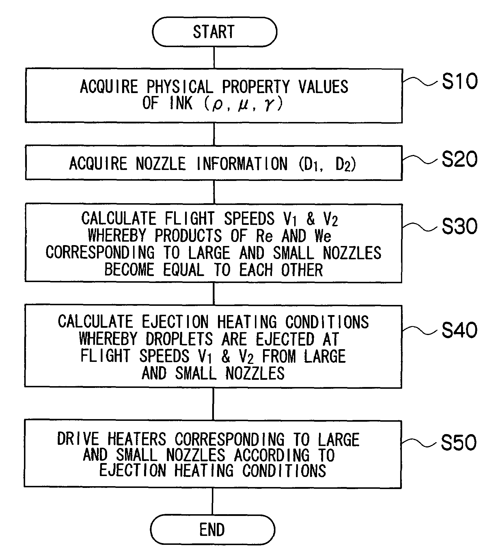
The present invention is an image forming apparatus that aims to achieve good image quality while reducing the computational load related to image processing. It includes a liquid ejection head with large and small nozzles that eject droplets of liquid. The ejection control device controls the ejection of droplets in such a way that the product of a Reynolds number and a Weber number for the droplets ejected from the large nozzle is equal to the product of a Reynolds number and a Weber number for the droplets ejected from the small nozzle. This results in similar shapes of dots formed by the droplets, leading to good image quality while reducing the computational load. The ejection control device also takes into account temperature-related variations in the physical properties of the liquid, such as density, viscosity, and surface tension. Additionally, the volume of the droplet ejected from the small nozzle should not be larger than 3 picoliters for optimal ejection control.

Problems solved by technology

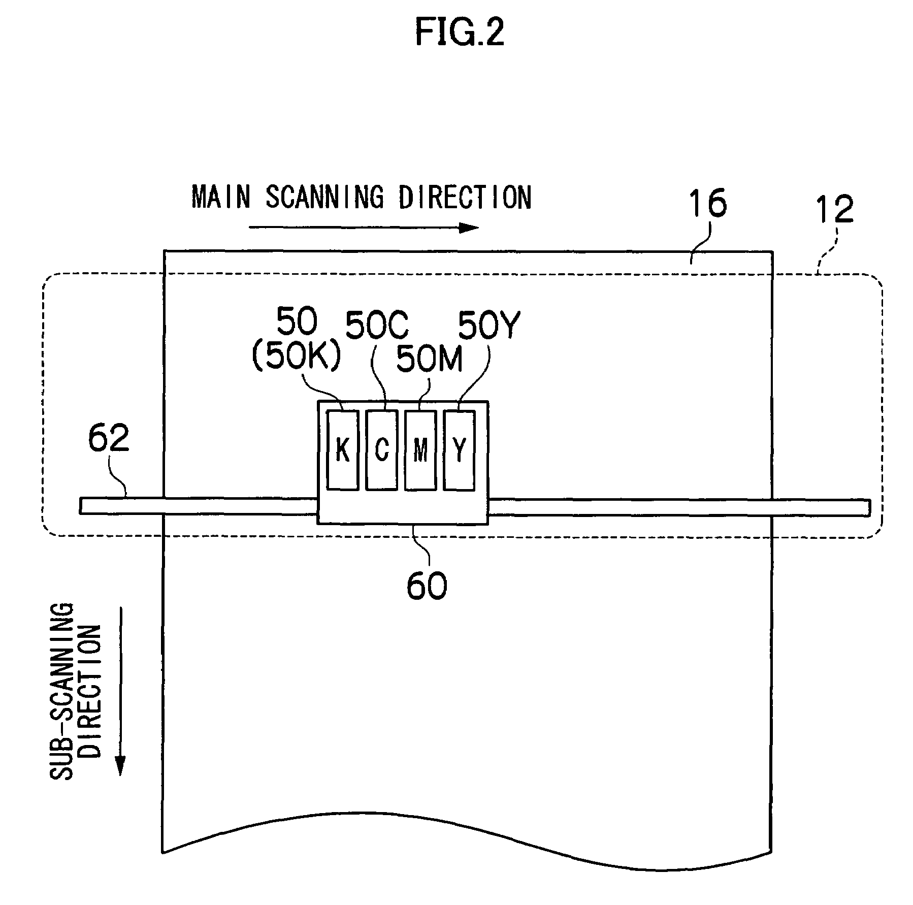
In particular, in a method which records by repeatedly moving the head in the breadthways direction of the recording medium (a serial scanning method), displacement arises in the deposition positions of the droplets, due to this difference in the flight speed, and hence there is a problem in that image deterioration occurs.
However, it has been found that there are limitations on the improvement of image quality that can be achieved by simply controlling the ejection timings of the large and small nozzles.
If the satellite droplets have a great effect in this way, then complicated calculation is required in the image processing, such as halftoning, and this creates major practical problems.

Method used


Image

  • Image forming apparatus
  • Image forming apparatus
  • Image forming apparatus

Examples


Embodiment Construction

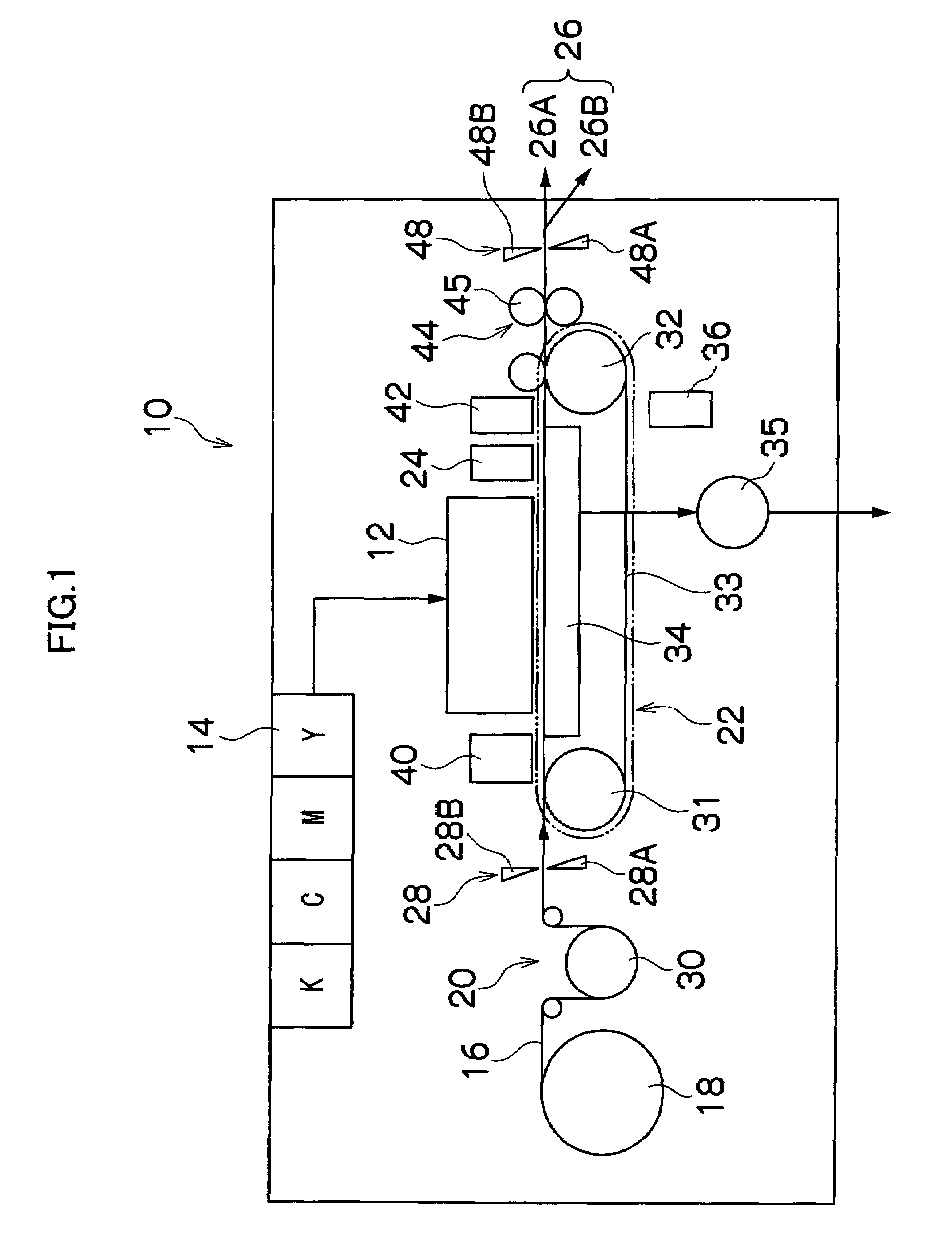
[0025]FIG. 1 is a general schematic drawing of an inkjet recording apparatus according to an embodiment of the present invention. As shown in FIG. 1, the inkjet recording apparatus 10 comprises: a print unit 12 having a plurality of heads (liquid ejection heads) provided for respective ink colors of black (K), cyan (C), magenta (M), and yellow (Y); an ink storing and loading unit 14 for storing inks to be supplied to the respective heads; a paper supply unit 18 for supplying recording paper 16; a decurling unit 20 for removing curl in the recording paper 16; a suction belt conveyance unit 22, disposed facing the ink ejection surface (nozzle surface) of the print unit 12, for conveying the recording paper 16 while keeping the recording paper 16 flat; a print determination unit 24 for reading the printed result produced by the print unit 12; and a paper output unit 26 for outputting printed recording paper (printed matter) to the exterior.

[0026]In FIG. 1, a magazine for rolled paper (...


PUM


Abstract

The image forming apparatus includes a liquid ejection head and an ejection control device. The liquid ejection head includes: a large nozzle and a small nozzle performing ejection of droplets of liquid, the droplet ejected from the large nozzle having volume larger than the droplet ejected from the small nozzle; and liquid flow channels corresponding to the large and small nozzles, the ejection of the droplets from the large and small nozzles being induced by formation of bubbles in the liquid in the corresponding liquid flow channels caused by applied thermal energy. The ejection control device controls the ejection of the droplets in such a manner that a product of a Reynolds number and a Weber number for the droplet ejected from the large nozzle and a product of a Reynolds number and a Weber number for the droplet ejected from the small nozzle are equal to each other. Each of the products is defined as:Re×We=ρ2×V3×D2μ×γ,where Re is the Reynolds number for the droplet, We is the Weber number for the droplet, ρ is a density of the liquid, V is a flight speed of the droplet, D is a diameter of the nozzle from which the droplet is ejected, μ is a viscosity of the liquid, and γ is a surface tension of the liquid.

Description

BACKGROUND OF THE INVENTION[0001]1. Field of the Invention[0002]The present invention relates to an image forming apparatus, and more particularly to an image forming apparatus having large nozzles and small nozzles which eject droplets having different volumes.[0003]2. Description of the Related Art[0004]In a thermal-jet type of inkjet recording apparatus, which ejects droplets by using thermal energy generated by heating elements, a recording head (hereinafter, simply called a “head”) having large nozzles and small nozzles which eject droplets of different volumes is used widely in order to achieve high-definition image recording. By varying the size (surface area) of the dots formed by the respective droplets ejected from the large and small nozzles, it is possible to represent a wide variety of densities.[0005]When using a head of this kind, the flight speed of the droplets ejected from the small nozzles is faster than the flight speed of the droplets ejected from the large nozz...

Claims


Application Information

Patent Timeline
Patent Type & Authority Patents(United States)
IPC IPC(8): B41J29/38B41J2/145
CPCB41J2/1404B41J2/1433B41J2002/14387
Inventor KUSUNOKI, NAOKI
Owner FUJIFILM CORP
Learn More