Multi-piece putter head having an insert

a multi-piece, insert technology, applied in the field of golf clubs, can solve the problems of large mallet heads that are not visually appealing to many golfers, putters that are pushed off the stroke plane on the backstroke, and can not be easily controlled during manufacturing, so as to avoid or minimize disadvantages, the force applied by threaded fasteners can be large, and the effect of easy control

Inactive Publication Date: 2009-07-28
DOGLEG RIGHT CORP
View PDF177 Cites 92 Cited by
  • Summary
  • Abstract
  • Description
  • Claims
  • Application Information

AI Technical Summary

Benefits of technology

[0017]Therefore, there is a need for a more forgiving putter with a large moment of inertia that is more traditional looking than most large mallet-style heads, and also swings more like a blade putter for improved ergonomic stroke mechanics, has increased confidence through familiar and pleasing design and optics, improved alignment, and improved energy transfer and ball launch and roll performance.
[0018]There is also a need for a golf club head with a traditional appearance, improved alignment features selectable by the user according to his or her tastes, including their needs for a new appearance, improved polar weighting and increased MOI, and means for selectively back-weighting while positively affecting the weight, balance, launch and roll dynamics.SUMMARY OF THE INVENTION
[0020]The present invention provides a multi-piece golf club head that can have a traditional blade-type base head portion, with an insert into the face that extends through an opening to the back of the putter, and a rearwardly extending portion extending behind the back of the base portion, which can include thereon an alignment aid and indicia by its shape and markings, and improved weight distribution. The rearwardly extending portion provides improved back-weighting, an increased area for hidden weight adjustment, and improved alignment through the shape of the rearwardly extending portion and the longer space for providing alignment indicia.
[0022]The base head portion can be fabricated similarly to a traditional blade-type putter head, preferably in denser weight material than the face insert and / or rearwardly extending portion of the through-head insert such as steel, and can include toe and heel weighting. The through-head insert, can be lightweight or lower density material and can be inserted and at least partially held in place by a press fit or other interference fit so that the striking face of the insert is flush mounted with the remaining striking face of the base putter head. However, to avoid or minimize disadvantages from relying solely on interference fit forces for retaining the through-head insert in place on the putter head portion, in the present invention, the through-head insert is retained at least in part by means other than an interference fit. These other means can include use of epoxy, and also can employ mechanical securing members such as threaded fasteners.
[0023]Threaded fasteners are advantageous for retaining the through-head insert in place for a number of reasons, including that the force applied by threaded fasteners can be large, and can be easily controlled during manufacturing. This makes it easier to ensure that the through-head insert and the putter head portion are securely held together under all conditions of use and play, minimizing the chance for the through-head insert to loosen due to rough handling or to have undesirable relative vibration between the through-head insert and the putter head portion during some playing conditions. Furthermore, although the threaded fasteners can be installed in a variety of positions, including above or below the insert, in one embodiment, the fasteners can be positioned such that they are generally perpendicular with the striking face, preferably entering from behind the striking face. This position for the fasteners also orients the force between the through-head insert and the putter head portion such that the force is generally perpendicular to the striking face; generally aligned with the direction of the putting stroke. This is believed to be advantageous in creating compressive stresses in the club face to resist impact forces upon striking the ball. This is also believed to assist in reducing the potential for bowing of the striking face of the through-head insert, caused by a high degree of interference force between them that might be caused if an interference fit alone was relied upon for securing the through-head insert to the base head portion.

Problems solved by technology

However, blade-type putter heads are not as forgiving or have as high a MOI as mallet type putters, whose large mass and rearward CG makes them more forgiving.
Such large mallet heads are not visually appealing to many golfers who prefer blade-type putters.
Also, depending on the placement of, and type of hosel or shaft connection, including how much offset and where the hosel or shaft is connected, as well as variables with the user's stroke mechanics, these large mallet heads can be awkward to swing and rotate properly in concert with the elliptical path of the stroke plane.
Too large an amount of mass in an aft-back location, too far away from the axis of the shaft can cause many golfers to have to overly manipulate the putter to maintain a proper face to plane relationship, or cause the putter to be pushed off the stroke plane on the backstroke.
This in turn can negatively affect the resultant forward stroke, the position and alignment of the putter head at contact, and therefore the accuracy and consistency of the results with such a putter design.
However, blade type putters generally have very short sighting lines due to their thin width face to back, and therefore are not as easy to align as larger mallets that contain longer sight lines or other indicia.
Furthermore, it is known that many golfers get tired of their putter when their performance with it is less than desirable.
Blade-type putters are also usually limited in the amount of weight that can be placed in the head due to their dense, thin structures.
Placing additional weights onto these heads, such as in the cavity, on the heel or toe or soles can negatively affect the appearance, balance and CG and performance of the putter.
None of the known prior art teaches the ability or a mechanism to fit or customize the Center of Gravity of a traditionally styled putter head, within the rules of golf, to suit an individual golfer's stroke mechanics and the resultant dynamic center of percussion, nor the ability to customize the length, shape or alignment indicia of a back-weight member to suit an individual golfer's preferences and needs for alignment shape and indicia.
The amount of the interference fit force is very sensitive to small changes in dimension of the through-head insert, the putter head portion and its opening, thus making it difficult to manufacture the multi-piece putter consistently with the same interference fit force between the through-head insert and the putter head portion in all putters under all conditions.
Thus, in some cases, it is possible that the force will be insufficient to hold the parts together if the putter head is dropped or otherwise roughly handled, for example, or to avoid undesirable relative vibration between through-head insert and the putter head portion under all playing conditions.
Furthermore, it is possible that the interference force can also tend to bow out the striking face to a small degree, which could interfere with manufacturing procedures as well as risking changing the flatness of the striking face.

Method used


Image

  • Multi-piece putter head having an insert
  • Multi-piece putter head having an insert
  • Multi-piece putter head having an insert

Examples


Embodiment Construction

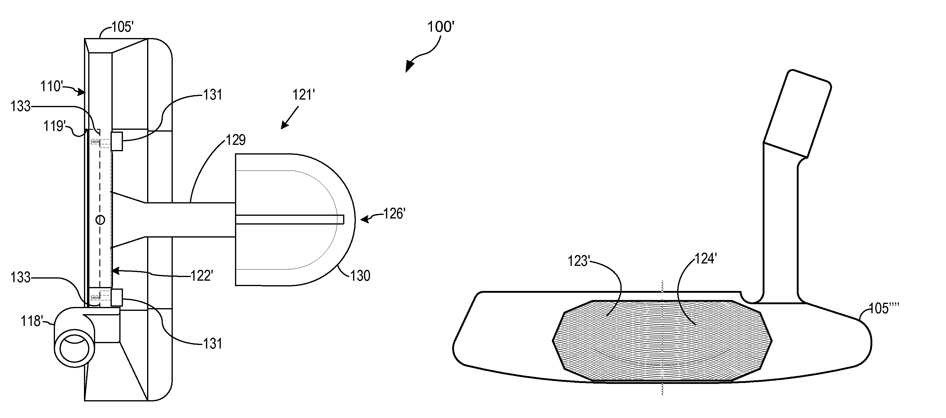
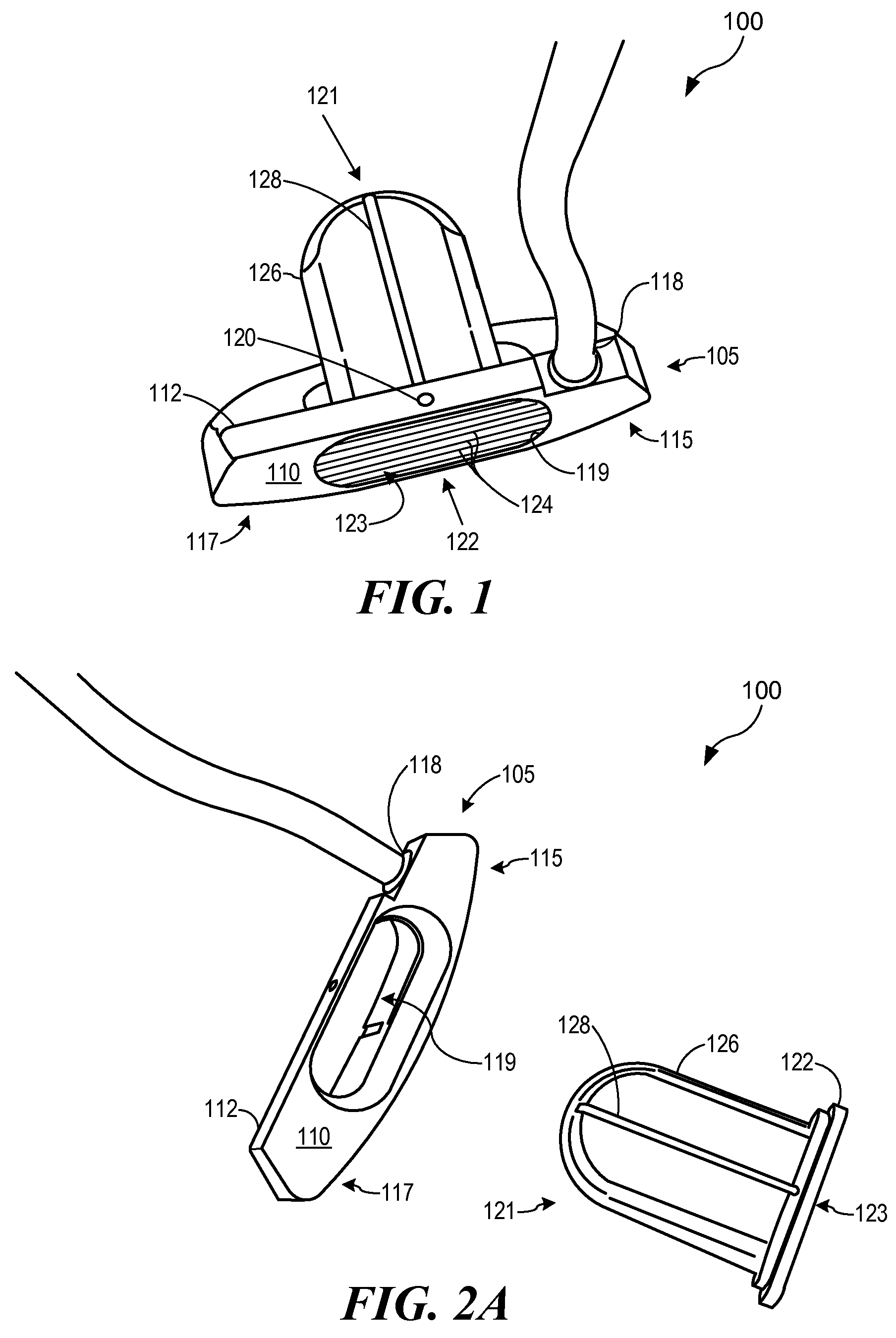
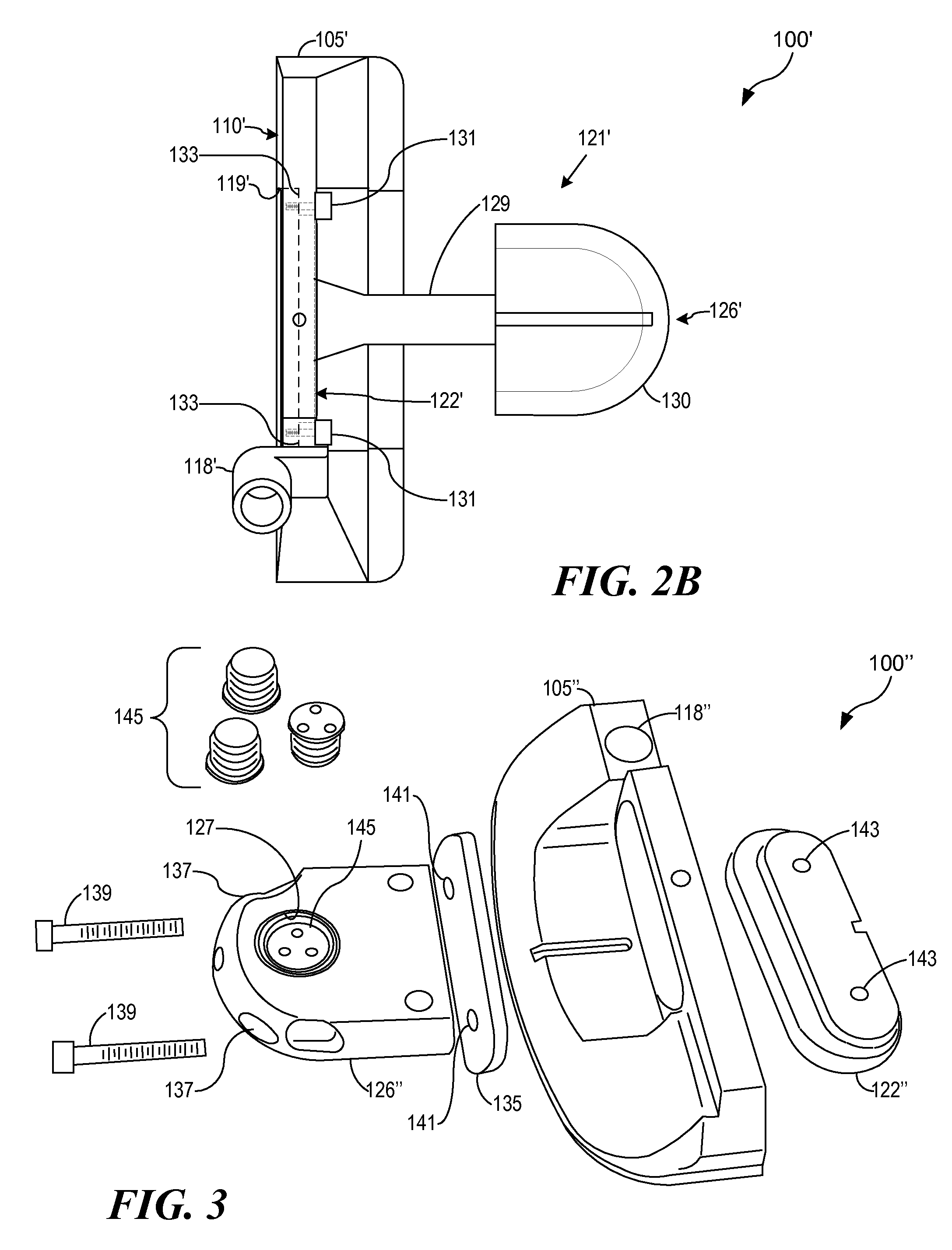
[0039]Referring to FIG. 1 of the drawings, the reference numeral 100 generally designates a golf club head embodying features of the present invention. The golf club head 100 may generally comprise a base head portion 105 having a face portion 110, a top-line portion 112, a heel portion 115, a toe portion 117 and a hosel portion 118. The golf club head 100 is shown in a generally finished state and includes an optional alignment mark 120. In this embodiment, the face portion 110 has an opening 119 through it, which opening 119 includes a through-head insert 121, which includes a front insert portion 122 that is preferably inserted flush with the surrounding face 110, and can be at least partially retained in place by a press-fit or other interference fit, but also in addition or in lieu thereof by other securing means. Through-head insert 121 includes a rearwardly extending portion 126 extending beyond that back of base head portion 105, and can optionally include alignment indicia ...


PUM


Abstract

A golf putter head with a front portion comprising traditional shape and appearance, with an integral face insert extending through the head to an alignment and weighting portion extending beyond the main body of the putter, adding improved alignment, increased MOI and adjustable weighting and adjustable balance and optimizable Center of Percussion. The putter head comprises a central face insert portion extending through the body and above the traditional weight flange, with mass relieved portions below the top of the alignment piece in order to receive one or more optional weights, and the upper side of the rearwardly extending portion being engraved or marked with various alignment indicia, and the whole through-head insert face portion and rearwardly extending portion being affixed to the base portion of the head at least in part with threaded fasteners.

Description

PRIOR APPLICATIONS[0001]This application claims the benefit of priority of the filing date of pending prior U.S. Provisional Application No. 60 / 792,181, entitled “Golf Club Face With Improved Face Pattern,” filed Apr. 14, 2006, and United States Utility Application No. 11 / 313,137, entitled “Customizable Center-of-Gravity Golf Club Head,” filed Dec. 20, 2005, which is a continuation of United States Utility Application No. 10 / 043,421, filed Jan. 10, 2002, now issued as U.S. Pat. No. 7,004,852, the contents of all of which are incorporated herein by reference.BACKGROUND OF THE INVENTION[0002]1. Field of the Invention[0003]The invention relates generally to golf clubs and, more particularly, to putter heads.[0004]2. Description of Related Art[0005]In recent years, a great amount of attention has been given by golf club designers, engineers, and manufacturers towards moving the weight and the center of gravity (CG) towards the polar extremes, increasing the moment of inertia (MOI) of th...

Claims


Application Information

Patent Timeline
Patent Type & Authority Patents(United States)
IPC IPC(8): A63B69/36A63B53/04A63B53/08
CPCA63B53/0487A63B53/065A63B2053/0416A63B2209/00A63B2053/0445A63B2053/022A63B2053/0491A63B2053/0441A63B53/0445A63B53/0441A63B53/0416A63B60/02
Inventor BILLINGS, DAVID P.
Owner DOGLEG RIGHT CORP
Why Eureka
Try Eureka