Sliding door arrangement

a sliding door and door frame technology, applied in the direction of doors/window fittings, walls, wing accessories, etc., can solve the problems of significant height difference, significant cumbersome roller-track arrangement, and inability to adjust the position of doors, so as to achieve convenient and efficient operation and improve durability.

Active Publication Date: 2009-08-04
HAWORTH SPA
View PDF17 Cites 34 Cited by
  • Summary
  • Abstract
  • Description
  • Claims
  • Application Information

AI Technical Summary

Benefits of technology

[0009]In the improved roller-track arrangement of this invention, as aforesaid, the bracket which couples the individual rollers to the door also have capability of permitting vertical adjustment of the upper edge of the door relative to the roller, which adjustment can be easily and efficiently carried out in a manner which is wholly independent of the mounting of the track to the associated support frame. The improved roller-track arrangement, as aforesaid, is also believed to provide improved durability, particularly with respect to impact loads which are typically imposed on the door during opening and closing thereof, and additionally includes structural and functional relationships which are believed to provide significantly improved characteristics with respect to its overall structure, performance and aesthetics, as described in greater detail hereinafter.

Problems solved by technology

While numerous sliding glass doors of the aforementioned type have been developed for use in this environment, nevertheless one of the problems associated with such doors has been the size and undesired aesthetics associated with the roller-track arrangement, which size and appearance are readily noticeable and hence have a significant impact on the overall aesthetics of the wall in view of the dominant glass construction of both the wall panels and the door.
In addition, many of the known sliding glass doors have not permitted easy positional adjustment of the door relative to the adjacent wall panels so as to provide desired alignment and aesthetics.
While this arrangement is conventional and does provide a proper rolling support and engagement between the rollers and track, nevertheless the overall combination of the track and rollers and their individual sizes and vertical disposition one above the other cause the overall roller-track arrangement to be of significant height.
As a result, the overall roller-track arrangement is significantly cumbersome, particularly with respect to its overall vertical height, and this greatly detracts from the desired overall appearance and aesthetics of the door-wall arrangement, particularly since visibility of the roller-track arrangement is effectively accentuated by the overall glass construction of both the door and the adjacent wall panels.
With this type of vertical adjustment capability, however, the manual manipulation required to effect vertical adjustment is typically difficult to carry out.
Further, and more significantly, such adjustment results in simultaneous adjustment of both the track and roller, and does not permit vertical adjustment of the roller independently of the track.

Method used


Image

  • Sliding door arrangement
  • Sliding door arrangement
  • Sliding door arrangement

Examples


Embodiment Construction

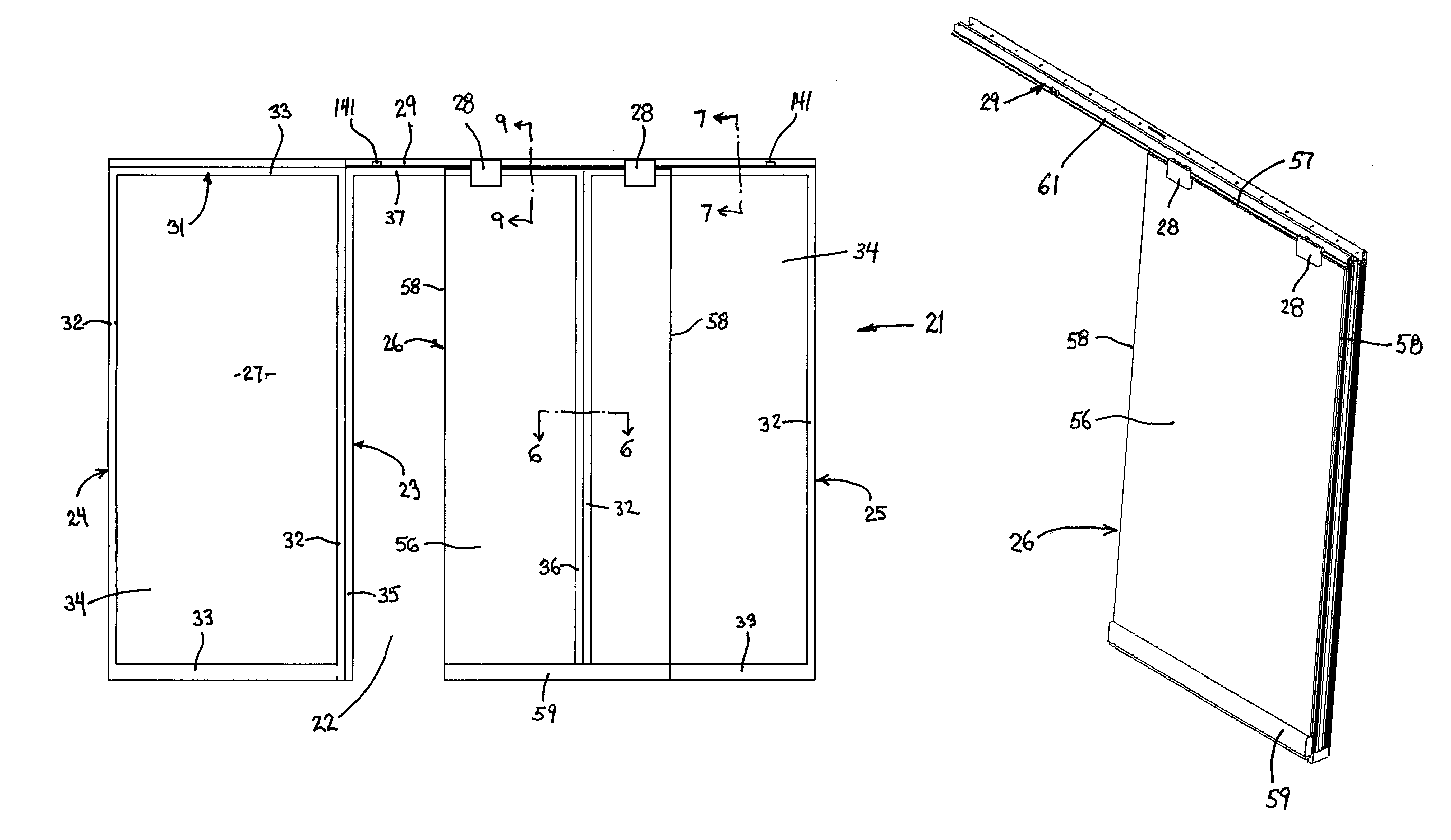
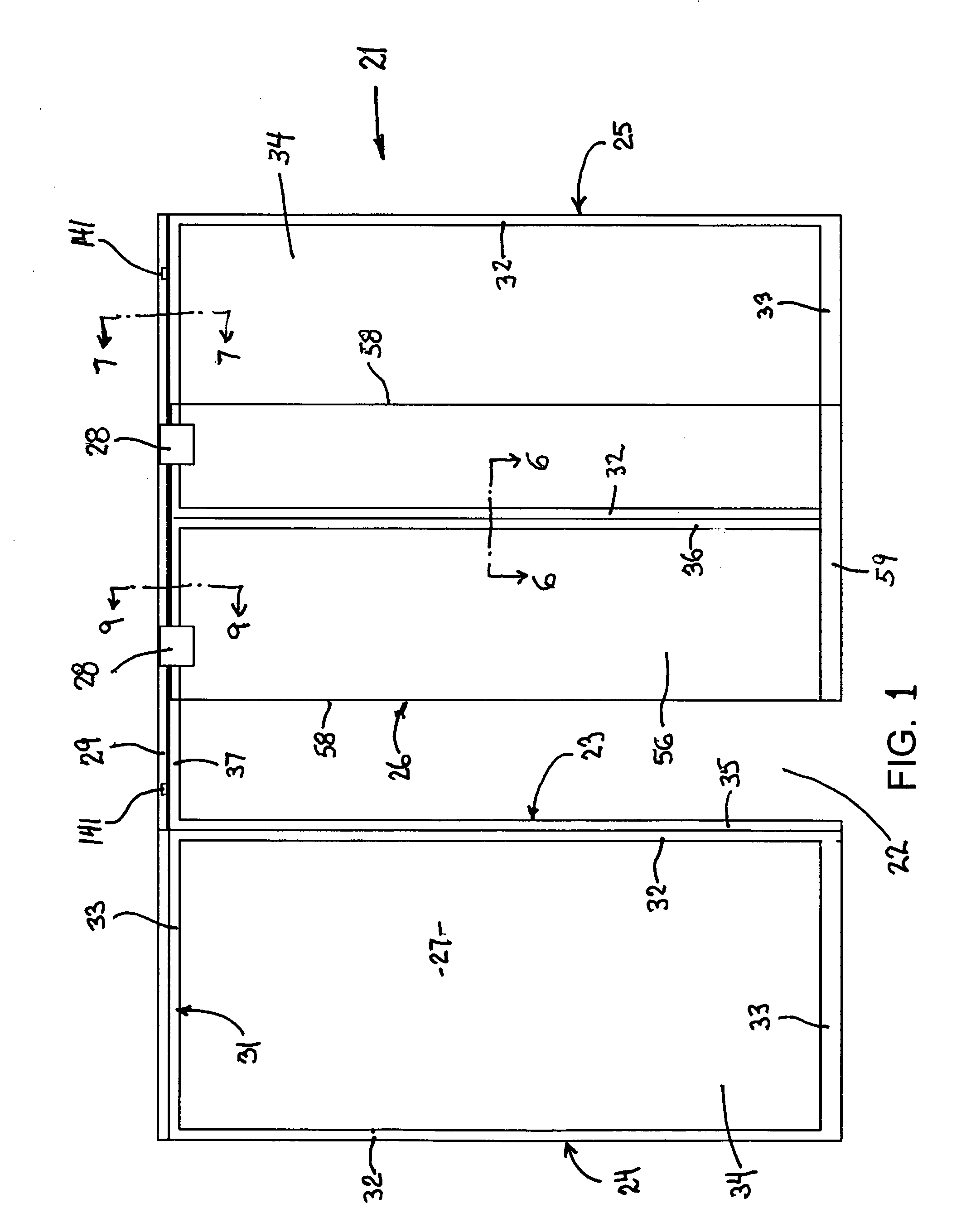
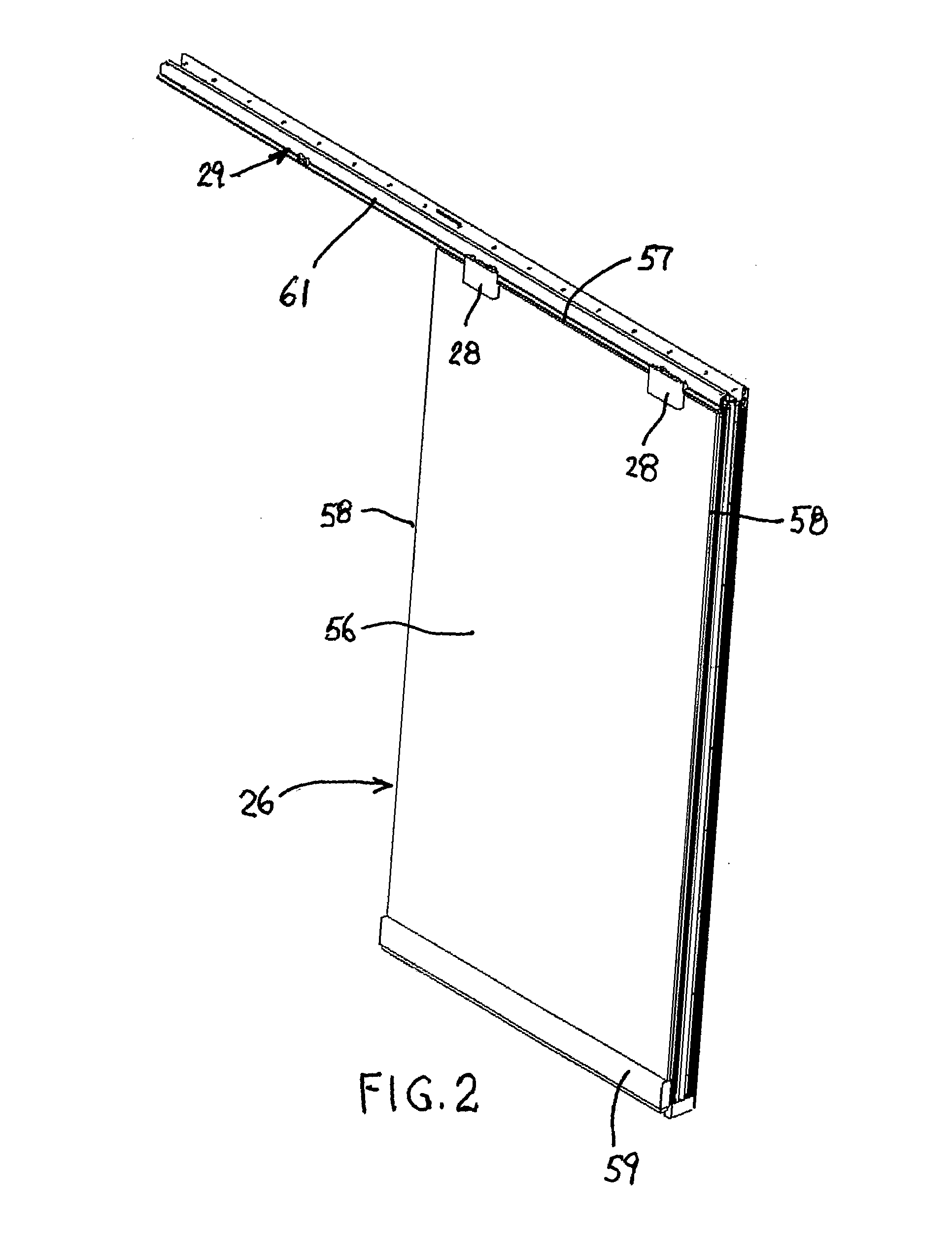
[0038]Referring to FIG. 1, there is illustrated an upright wall arrangement 21 which is typically intended for support on a floor within a building, and which cooperates with additional fixed or prefabricated moveable walls to assist in dividing a large open area into smaller areas used for offices and the like. The upright wall 21 in the illustrated arrangement has a doorway 22 associated therewith for permitting passage between adjacent areas, such as between a hallway and an adjacent office. The doorway or passage 22 is in the present invention defined by an inverted U-shaped door frame 23 which is disposed in sidewardly aligned relationship with, and joined to, a pair of sidewardly adjacent upright wall panels 24 and 25. The upright wall 21 has a vertically suspended sliding door 26 associated therewith. The sliding door 26 is disposed in laterally adjacent and generally overlapping relationship to one exposed side 27, herein referred to as the front side, of the upright wall. T...


PUM


Abstract

A sliding glass door has a pair of rollers mounted adjacent the upper corners, which rollers are cantilevered rearwardly and cooperate with a horizontally elongate L-shaped support track which spans horizontally across the door opening and across an adjacent upright wall panel to enable the door to move into an opened position wherein it overlies the adjacent wall panel. The height of the roller-track arrangement and of the structure defining such arrangement, as it extends across the upper edge of the door opening and the adjacent wall panel, is minimized to provide improved aesthetics.

Description

FIELD OF THE INVENTION[0001]This invention relates to a sliding door arrangement and, more specifically, relates to an improved roller-track arrangement which cooperates with an upper edge of a glass sliding door for maintaining the door in a suspended position while permitted movement of the door between opened and closed positions.BACKGROUND OF THE INVENTION[0002]Sliding doors which are dominantly of glass and are downwardly suspended from a roller-track arrangement which couples the door to the adjacent wall or ceiling are currently used in association with walls for dividing interior office spaces and the like, and there is increased demand for such sliding glass doors for use in conjunction with upright walls defined by a plurality of generally prefabricated wall panels which are dominantly of glass and are horizontally serially joined. The sliding glass door is typically supported from the wall so as to be positioned laterally adjacent one exterior side face of the wall, and t...

Claims


Application Information

Patent Timeline
Patent Type & Authority Patents(United States)
IPC IPC(8): E05D15/16E06B1/04
CPCE04B2/7455E05D15/063E05Y2900/132E05Y2800/672E05Y2201/614
Inventor SHIVAK, VINCENT A.JAKOB-BAMBERG, RUPERTSTEEVES, ROBERT E.
Owner HAWORTH SPA
Why Eureka
Try Eureka