
Sleeve and coupler for electronic device

a technology for electronic devices and couplers, which is applied in the direction of coupling device connections, electrical apparatus casings/cabinets/drawers, couplings, etc., can solve the problems of usb connectors and/or ports being damaged, the prior art patents not solving the needs of this art, and the connection is vulnerable to damag

Inactive Publication Date: 2009-08-04
MICHAEL G LANNON
View PDF60 Cites 62 Cited by
  • Summary
  • Abstract
  • Description
  • Claims
  • Application Information

AI Technical Summary

Benefits of technology

[0032]In a more specific embodiment of the invention, the housing contains a portable memory electrically communicating with the plug. The contoured body cross section of the body and the contoured wall cross section of the receptacle has a non-symmetrical cross section for permitting inserting and keying of the housing into the receptacle in only one orientation. The exterior end of the receptacle includes a guide having an interior aperture, an exterior aperture and a conical surface positioned therebetween. The interior aperture of the guide is positioned within the wall surface. The exterior aperture of the guide is commensurate to the

Problems solved by technology

Since the USB connector extends outside of the plastic or metal casing, the connector is vulnerable to damage by striking a foreign object or intrusion of particles or moisture.
If the casing is stuck while the casing is engaged with the port on a personal computer, the USB connector and / or the port may be damaged.
Although the aforementioned prior art have contributed to the development of the art of shielding and coupling, none of these prior art patents have solved the needs of this art.

Method used


Image

  • Sleeve and coupler for electronic device
  • Sleeve and coupler for electronic device
  • Sleeve and coupler for electronic device

Examples


Embodiment Construction

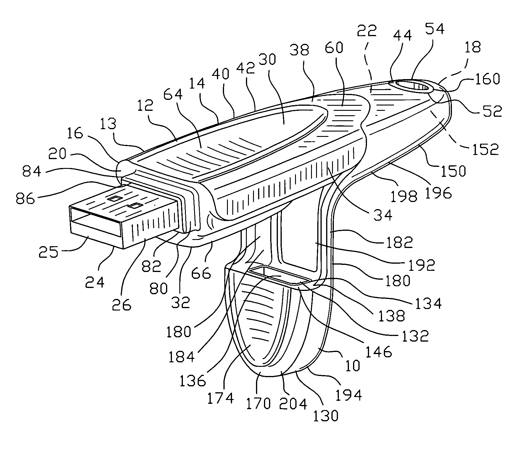
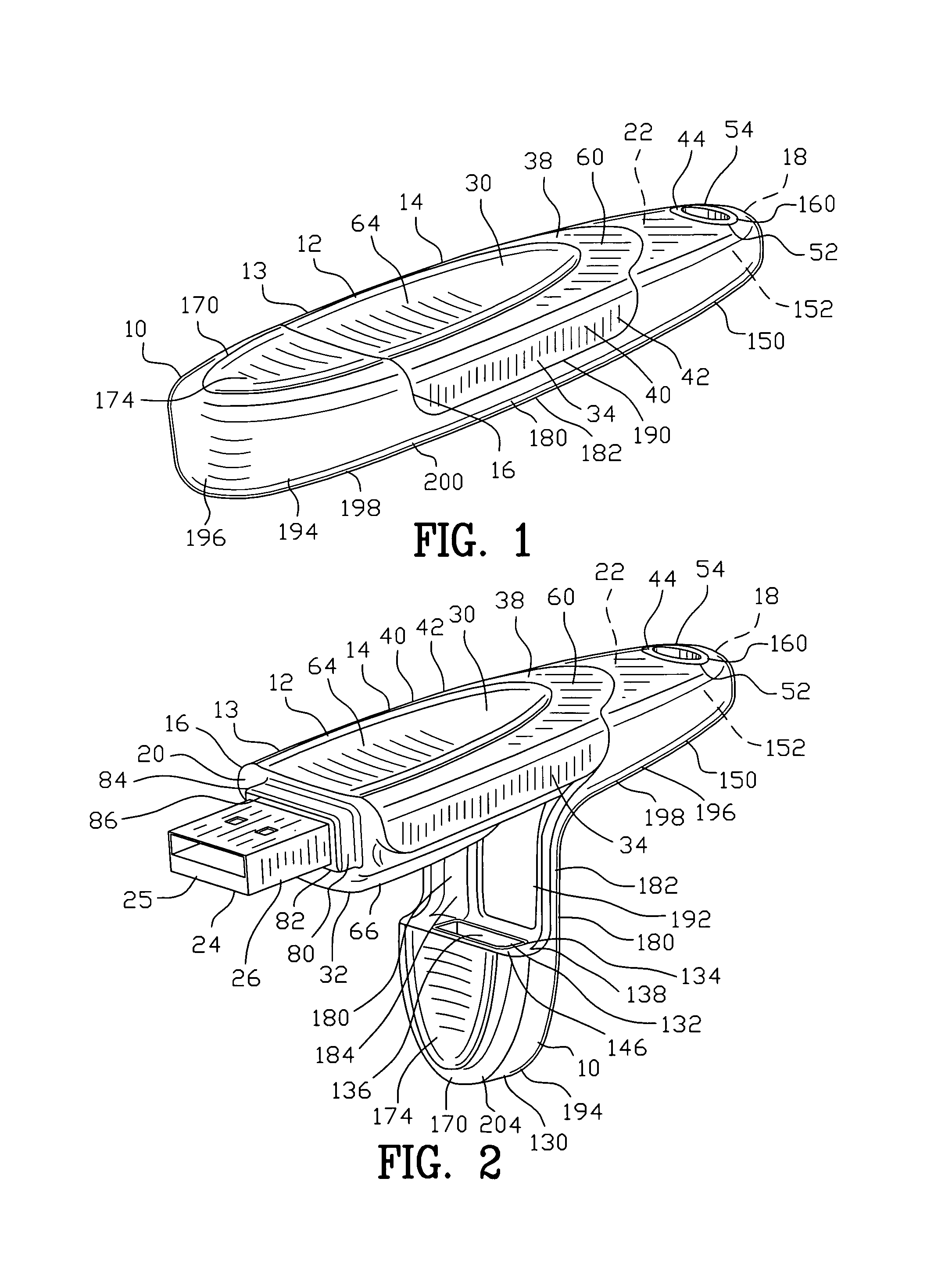
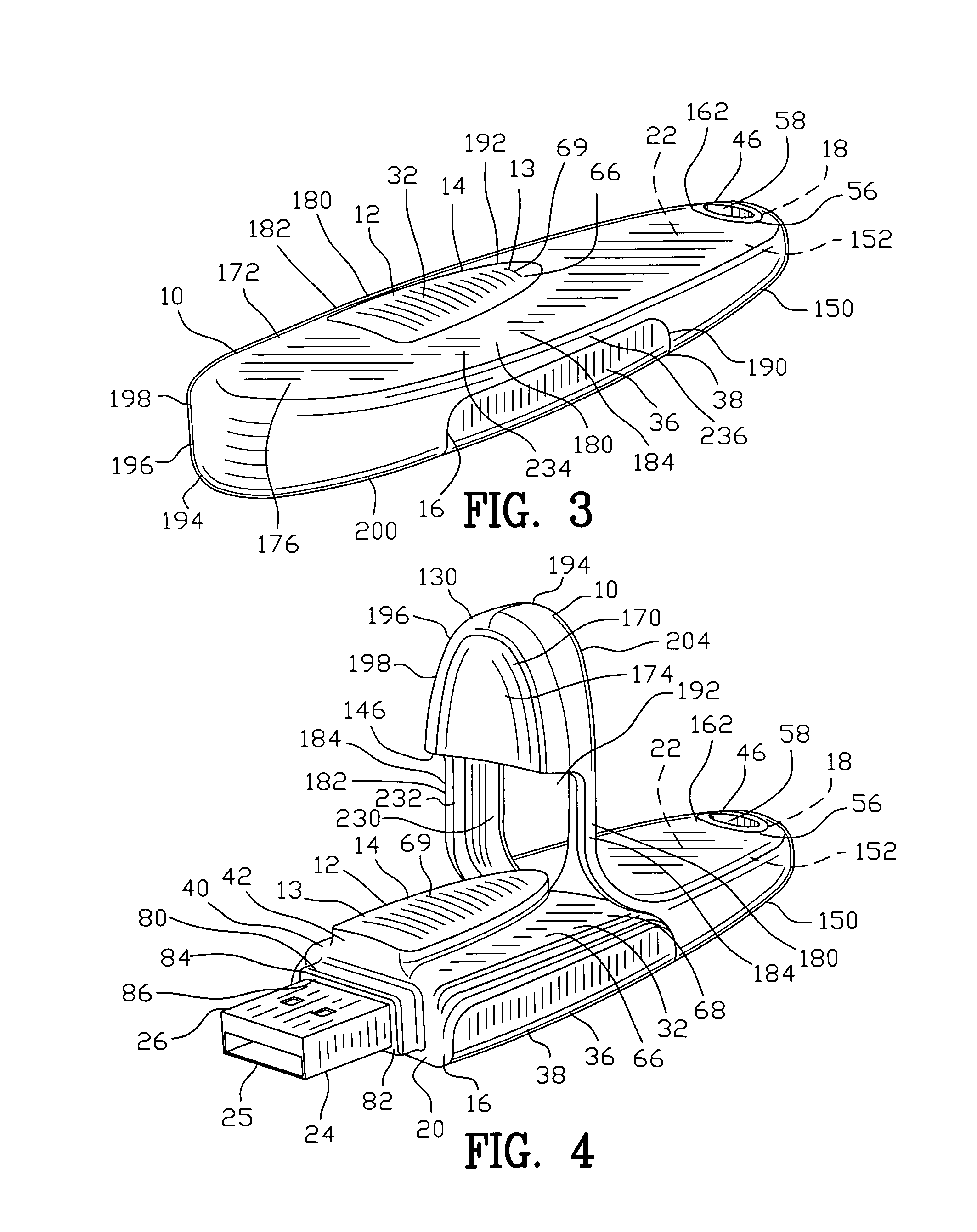
[0128]FIGS. 1-10 are various views of a sleeve 10 for engaging an electronic device 12. The electronic device 12 may be a USB flash memory device 13. The electronic device 12 may include other electronic devices such as a USB WiFi antenna or other USB devices.

[0129]FIGS. 1-35 are various views of the electronic device 12 including a housing 14 having a first end 16 and a second end 18. The first end 16 of the housing 14 defines a housing engaging surface 20 and the second end 18 of the housing 14 defines a housing support surface 22. A plug 24 extends from the housing engaging surface 20 of the housing 14. The plug defines an input end 25 distanced from the housing engaging surface 20 by a neck 26. As best seen in FIGS. 86-91, the plug 24 engages a computer device 28 for transferring data between the electronic device 12 and the computer device 28.

[0130]The housing 14 further includes a top surface 30 and a bottom surface 32. The top surface 30 and the bottom surface 32 are distance...


PUM


Abstract

A sleeve is disclosed for engaging an electronic device. The electronic device includes a housing with a plug extending therefrom. The housing has an engaging surface and a housing support surface. The sleeve comprises a plug cap for receiving the plug. A housing cap includes a cavity for receiving the housing. An elastic tether extends between the plug cap and the housing cap for securing the plug cap to the housing cap. The elastic tether is deformable for providing a first length during the plug cap engaging the plug. The elastic tether is deformable for providing a second length during the plug cap displaced above the plug. The elastic tether being is deformable for providing a third length during said plug cap removed from the plug. A coupling is disclosed for joining an electronic device and a computer device. The coupling comprises a housing having a first end, a second end and a body. The body defines a contoured body cross section. A receptacle has an interior end, an exterior end and a wall surface. The wall surface defines a contoured wall cross section. The contoured body cross section is commensurate with the contoured wall cross section for inserting and keying the housing into the receptacle.

Description

CROSS-REFERENCE TO RELATED APPLICATIONS[0001]This application claims benefit of U.S. Patent Provisional application Ser. No. 60 / 899,900 filed Feb. 7, 2007. All subject matter set forth in provisional application Ser. No. 60 / 899,900 is hereby incorporated by reference into the present application as if fully set forth herein.BACKGROUND OF THE INVENTION[0002]1. Field of the Invention[0003]This invention relates to shielding and coupling and more particularly to an improved apparatus for shielding an electronic storage device and an improved apparatus for coupling an electronic device to a computer device.[0004]2. Background of the Invention[0005]USB flash drives are memory data storage devices integrated with a USB interface. USB flash drives are preferable over many other data storage devices in that the USB flash drives are typically small, lightweight, removable and rewritable. The USB flash drives consist of a small printed circuit board encased in a plastic or metal casing. A USB...

Claims


Application Information

Patent Timeline
IPC IPC(8): H01R13/52
CPCH01R13/5213H05K5/0278H01R31/065
Inventor LANNON, MICHAEL G.OBANA, MARYSPOETH, JR., CARL R.PEARSON, JEFFREY A.
Owner MICHAEL G LANNON
Features
  • Generate Ideas
  • Intellectual Property
  • Life Sciences
  • Materials
  • Tech Scout
  • Unparalleled Data Quality
  • Higher Quality Content
  • 60% Fewer Hallucinations
Learn More