Switch assembly having non-planar surface and activation areas

a technology of non-planar surfaces and switches, applied in the field of switches, can solve the problems of affecting the convenient use of electronic devices, affecting the physical selection and touch of users, and the size of electronic devices is becoming smaller and smaller

Inactive Publication Date: 2009-08-04
QUALCOMM INC
View PDF39 Cites 6 Cited by
  • Summary
  • Abstract
  • Description
  • Claims
  • Application Information

AI Technical Summary

Benefits of technology

[0010]An advantage of the switch assembly in accordance with the present invention is that the non-planar surfaces of the switch assembly make it easy for the switch assembly to be used. For example, one may center a thumb or other finger in the concavity of the central switch to select the central switch. It is easy to feel where the second switches are located because they have convex surfaces in contrast to the concave surface of the central switch; by sliding one's finger over from the central switch to the second switches, one gets tactile feedback that the finger moved to another switch or control area. Similarly, it is easy to feel where the third switches and their activation areas are located, because the third switches have flat (planar) surfaces and their activation areas have concave or convex surfaces; by sliding one's finger over from the second switches to the third switches and especially their concave or convex activation areas, one gets tactile feedback that the finger moved to another switch or control area.

Problems solved by technology

Modem electronic devices are provided with a large number of functions, but at the same time the size of the electronic devices is becoming smaller and smaller.
Thus, it is a challenge to provide a sufficient number of control switches that can be used to navigate through the user interfaces in the graphical user interfaces of the electronic devices and operate the provided functionalities without occupying a large area of the electronic devices.
However, this may interfere with the convenient use of the electronic devices, because it becomes more difficult for a user to physically select and touch a particular switch due to the small size of the switch and its proximity to other switches.
For example, a user may intend to select and activate a particular one of the switches but end up accidentally activating a different one of the switches due to the small size of the particular switch and its proximity to the other different switches.

Method used


Image

  • Switch assembly having non-planar surface and activation areas
  • Switch assembly having non-planar surface and activation areas
  • Switch assembly having non-planar surface and activation areas

Examples


first embodiment

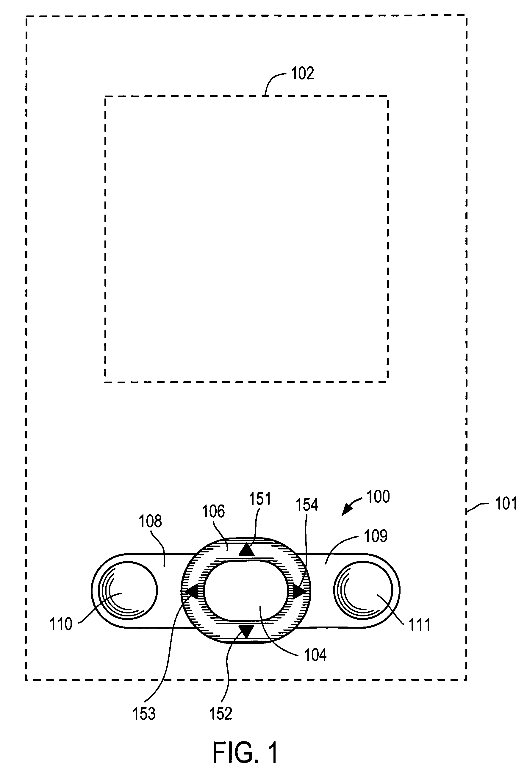
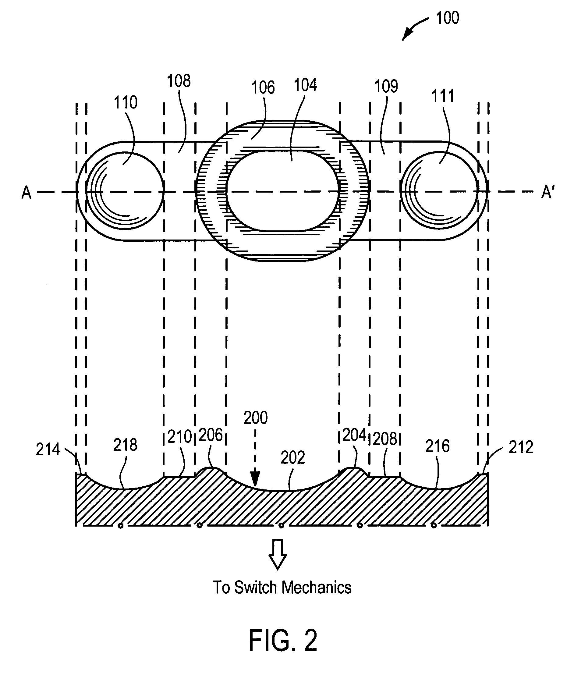
[0023]FIG. 1 is illustrates an electronic device 101 with a switch assembly in accordance with the present invention. The electronic device 101 may be any type of electronic device that requires the use of switches, for example, a PDA, a cellular telephone, a portable media player, a smartphone, a PDA phone, a mobile manager, a portable computer, etc. The electronic device 101 includes a display 102 and a switch assembly 100 for navigating through the user interface and selecting certain items shown in the display 102 or activating certain applications of the electronic device 101.

[0024]The switch assembly includes a central switch 104, a navigational ring switch 106 adjacent to and surrounding the central switch 104, and two additional switches 108, 109 adjacent to the navigation ring switch 104 and positioned on the left and right sides of the navigational ring switch 106. In one embodiment, the central switch 104 is typically used to select or activate applications or other items...

fifth embodiment

[0035]FIG. 5 illustrates switch assemblies 500, 502, 504 in accordance with the present invention. The switch assembly 500 is functionally identical to the switch assembly 100 shown in FIGS. 1-3, but structurally differs by integrating two switch regions 510, 512 enclosing the navigational ring switch 106. The switch region 510 includes two concave activation areas 514, 518, and the switch region 512 includes two concave activation areas 516, 520. The switch assembly 502 is identical to the switch assembly 500, except that it has smoother edges at the outer corners 530, 532, 534, 536 of the switch regions 510′, 512′. The switch assembly 504 is identical to the switch assembly 500 except that it has even smoother (almost round) edges at the outer corners 538, 539, 540, 542 of the switch regions 510″, 512″.

sixth embodiment

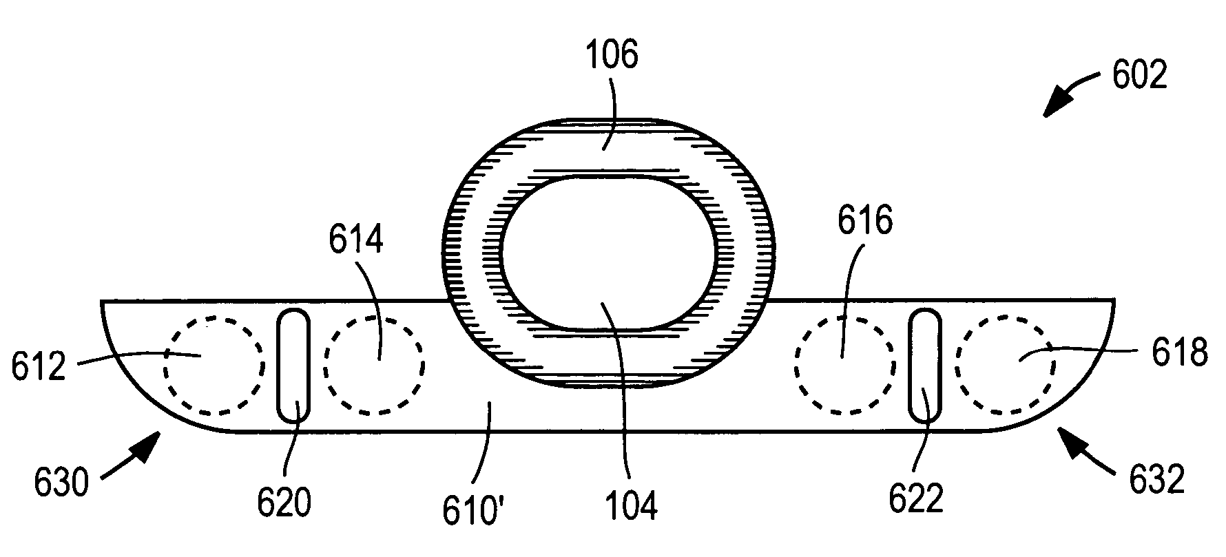
[0036]FIG. 6 illustrates switch assemblies 600, 602 in accordance with the present invention. The switch assembly 602 is functionally identical to the switch assembly 100 shown in FIGS. 1-3, but structurally differs by integrating a switch region 610 enclosing a bottom half of the navigational ring switch 106. The switch region 610 includes four concave activation areas 612, 614, 616, 618, where two of the activation areas 612, 614 are separated by a convex divider 620, and the other two of the activation areas 616, 618 are separated by another convex divider 622. The convex dividers 620, 622 serve as “speed bumps” such that one can tactically feel and distinguish between two activation areas 612, 614 or 616, 168 that are positioned close to each other. Although the switch region 610 encloses only the bottom half of the navigational ring switch 106 in the example of FIG. 6, note that the switch region 610 can be modified to enclose the upper half or the entire navigational ring swit...


PUM


Abstract

A switch assembly includes a central first switch with a concave surface, a plurality of second switches adjacent to and surrounding the central switch in an elliptical or circular shape, where the second switches form a convex surface, and a plurality of third switches adjacent to the second switches in an outer side of the elliptical or circular shape of the second switches, where the third switches include activation areas with concave surfaces and with flat surfaces outside the activation areas. The third switches can include two switches, one of which is located at one end and the other one of which is located at the opposite end of the elliptical or circular shape of the second switches. The non-planar surfaces of the switch assembly enable one to easily feel the locations of the switches and to get tactile feedback when the finger moved to another switch area.

Description

BACKGROUND OF THE INVENTION[0001]1. Field of the Invention[0002]The present invention relates to switches, and more specifically, a switch assembly having non-planar surfaces and activation areas.[0003]2. Description of the Related Art[0004]Modem electronic devices are provided with a large number of functions, but at the same time the size of the electronic devices is becoming smaller and smaller. Thus, it is a challenge to provide a sufficient number of control switches that can be used to navigate through the user interfaces in the graphical user interfaces of the electronic devices and operate the provided functionalities without occupying a large area of the electronic devices.[0005]It may be possible to place many control switches in a small area, which would require making the switches smaller and positioning the switches closer to each other. However, this may interfere with the convenient use of the electronic devices, because it becomes more difficult for a user to physica...

Claims


Application Information

Patent Timeline
Patent Type & Authority Patents(United States)
IPC IPC(8): H01H9/02
CPCG06F1/1626G06F1/169H01H25/041H01H25/008H01H2217/024
Inventor LAM, LAWRENCECEBE, CHROME
Owner QUALCOMM INC
Why Eureka
Try Eureka