Method and installation for detecting and following an eye and the gaze direction thereof

a technology for tracking eyes and eye angles, applied in the field of methods and installation for tracking eyes and gaze angles/directions, can solve the problems of often significantly larger parallax distortion than is acceptable in many applications, and achieve the effect of efficient installation

Active Publication Date: 2009-08-11
TOBII TECH AB
View PDF6 Cites 223 Cited by
  • Summary
  • Abstract
  • Description
  • Claims
  • Application Information

AI Technical Summary

Benefits of technology

[0010]It is an object of the invention to provide an efficient method and an efficient installation for detecting and tracking eyes and gaze angles / directions.

Problems solved by technology

This parallax distortion is often significantly larger than what is acceptable in many applications.

Method used


Image

  • Method and installation for detecting and following an eye and the gaze direction thereof
  • Method and installation for detecting and following an eye and the gaze direction thereof
  • Method and installation for detecting and following an eye and the gaze direction thereof

Examples


Embodiment Construction

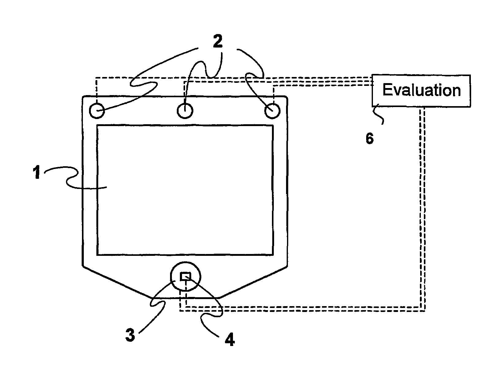
[0034]In FIG. 1 an installation for determining the point on a monitor 1 at which a computer user is looking / gazing is shown. The determination is performed by tracking the eyes of the user and in particular by determining the gaze angles of the eyes and the distance of the eyes from the monitor. The installation includes the monitor 1, three identical light sources 2 mounted along a straight line at the upper edge of the monitor 1, a photosensor 4 placed at the center of the bottom edge of the monitor and provided with a suitable optical system, not shown, that is located in front of the photosensor for both filtering away undesired light and for focusing a picture on the light sensitive surface of the photosensor, and a light source 3 placed coaxially with the optical axis of the photosensor, i.e. located around, at all sides of, the light sensitive surface of the photosensor. The light sensitive surface can, as shown, have a rectangular shape. The coaxial light source 1 includes,...


PUM


Abstract

When detecting the position and gaze direction of eyes, a photo sensor (1) and light sources (2, 3) placed around a display (1) and a calculation and control unit (6) are used. One of the light sources is placed around the sensor and includes inner and outer elements (3′; 3″). When only the inner elements are illuminated, a strong bright eye effect in a captured image is obtained, this resulting in a simple detection of the pupils and thereby a safe determination of gaze direction. When only the outer elements and the outer light sources (2) are illuminated, a determination of the distance of the eye from the photo sensor is made. After it has been possible to determine the pupils in an image, in the following captured images only those areas around the pupils are evaluated where the images of the eyes are located. Which one of the eyes that is the left eye and the right eye can be determined by following the images of the eyes and evaluating the positions thereof in successively captured images.

Description

[0001]This application is the US national phase of international application PCT / SE2003 / 001813 filed 21 Nov. 2003 which designated the U.S. and claims priority of SE 0203457-7, filed 21 Nov. 2002, the entire contents of each of which are hereby incorporated by reference.RELATED APPLICATION[0002]This application claims priority and benefit from Swedish patent application No. 0203457-7, filed Nov. 21, 2002, the entire teachings of which are incorporated herein by reference.TECHNICAL FIELD[0003]The present invention relates a method and an installation for detecting and tracking eyes and gaze angles / directions. Such a system can for example be used for observing or determining the position on a monitor or display at which a computer user is looking.BACKGROUND[0004]Monitoring or tracking eye movements and gaze points can be used in many different contexts. Information about the position at which a person is looking can be used for analyzing the behavior and consciousness of the person. ...

Claims


Application Information

Patent Timeline
Patent Type & Authority Patents(United States)
IPC IPC(8): A61B3/14G03B17/00A61B3/113
CPCA61B3/113G06V40/19
Inventor ELVESJO, JOHNSKOGO, MARTENELVERS, GUNNAR
Owner TOBII TECH AB
Why Eureka
Try Eureka