Anchoring barb for attachment to a medical prosthesis

a technology for attaching barbs and prostheses, which is applied in the field of medical devices, can solve the problems of reducing the overall effect of metal microstructure, corrosion and/or breakage of solder joints, and achieves the effects of reducing costs, reducing overall effects of metal microstructure, and more uniform and consistent results in manufacturing and performan

Active Publication Date: 2009-08-11
COOK MEDICAL TECH LLC
View PDF21 Cites 109 Cited by
  • Summary
  • Abstract
  • Description
  • Claims
  • Application Information

AI Technical Summary

Benefits of technology

[0007]In another aspect of the invention, the anchoring element comprises a helix configuration formed from cannula or a flat sheet of material. The helix wraps around the strut of the prosthesis and spaces between the windings provide convenient points for laser weld to affix the anchoring element, thus limiting the extent of weld annealing around the basal region of the barb.
[0008]In still another aspect of the invention, the anchoring element is slidably disposed on the strut rather than being permanently affixed. The cannula, or anchoring element formed from flat stock is inserted over or around the strut. Stops that are either attached to, incorporated into the strut, or occur as part of the frame design, limit the longitudinal movement of the anchoring element. By allowing the anchoring element comprising the barb to move in response to forces concentrated at a particular anchor point, it will be less likely to cause the barb to fracture and perhaps lead to migration of the prosthesis. Additionally, a slidable barb can be advantageously configured as a deployable barb system where the barb assumes a first configuration not adapted to engage tissue, such as for the delivery or initial placement of the prosthesis, but is then manipulated into a second configuration or orientation to penetrate the adjacent tissue, such as the luminal wall, and anchor the prosthesis. In a first exemplary embodiment of the present invention, the slidable anchoring element which includes a barb generally extending parallel with the strut, is attached to a actuating system, such as a tether, which urges the anchoring element over the strut until it contacts a deflecting element, such as a ramped structure, located on the strut which forces the barb outward into a position that is better able to penetrate tissue. Optionally, the anchoring element is configured to engage structure located on the strut that locks the anchoring element into the second, engageable position. In a second embodiment, the prosthesis can be deployed with the barb oriented away from the tissue surface, whereby the anchoring element and barb are rotated or otherwise urged or moved into position after the prosthesis is deployed at the implantation site such that the barb tip is able to embed into the adjacent tissue and further anchor the device. Actuation of the anchoring element can be done with releasable tethers, sleeves, sheaths or other mechanisms that restrain the barbs in an inward or otherwise non-engaging orientation, whereby the restraint is released to allow the anchoring element and barbs to resiliently rotate or slide to assume a tissue-engaging position. Spiral threads or grooves, or a twisted strut (e.g., preferable with a non-rounded strut profile) can be used to guide the anchoring element from the first non-engaging position to the second, engageable position. Tethers, wires, pushers, or other mechanical structure may be used to urge the anchoring elements and barbs from a non-engaging position (e.g., via rotation or longitudinal movement of the anchoring element) to one that allows the barbs to penetrate and anchor the device once the prosthesis is in position for final deployment.
[0009]Optionally, the anchoring element and strut can be configured such that they slidably engage one another in a manner that limits axial rotation of the anchoring element, thereby ensuring that the barb remains in the desired plane for optimum functionality. This can be accomplished by a variety of methods, including conforming the anchoring element over an at least partially squared strut or having the anchoring element and strut engage one another, such as fitting a tab within a longitudinal groove or other structure, which limits the ability of the anchoring element to twist on the strut while still allowing it to slide longitudinally.

Problems solved by technology

The disadvantages of using solder include corrosion and / or breakage of the solder joint.
Additionally, soldering results in heat being dispersed over a large area of the frame, while laser or spot welding can better concentrate the heat to a more precise location, thus limiting its overall affects on the microstructure of the metal.

Method used


Image

  • Anchoring barb for attachment to a medical prosthesis
  • Anchoring barb for attachment to a medical prosthesis
  • Anchoring barb for attachment to a medical prosthesis

Examples


Embodiment Construction

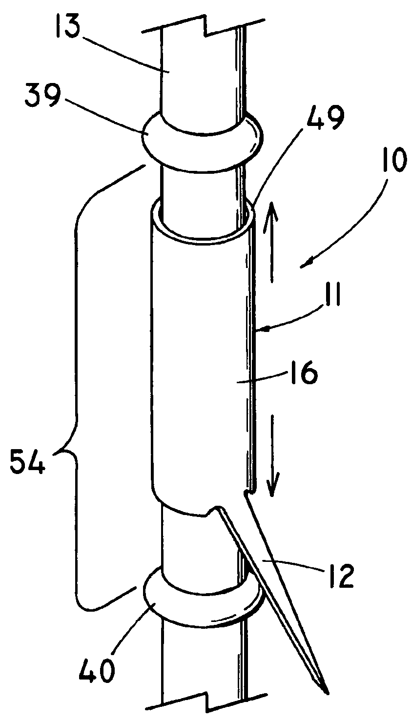
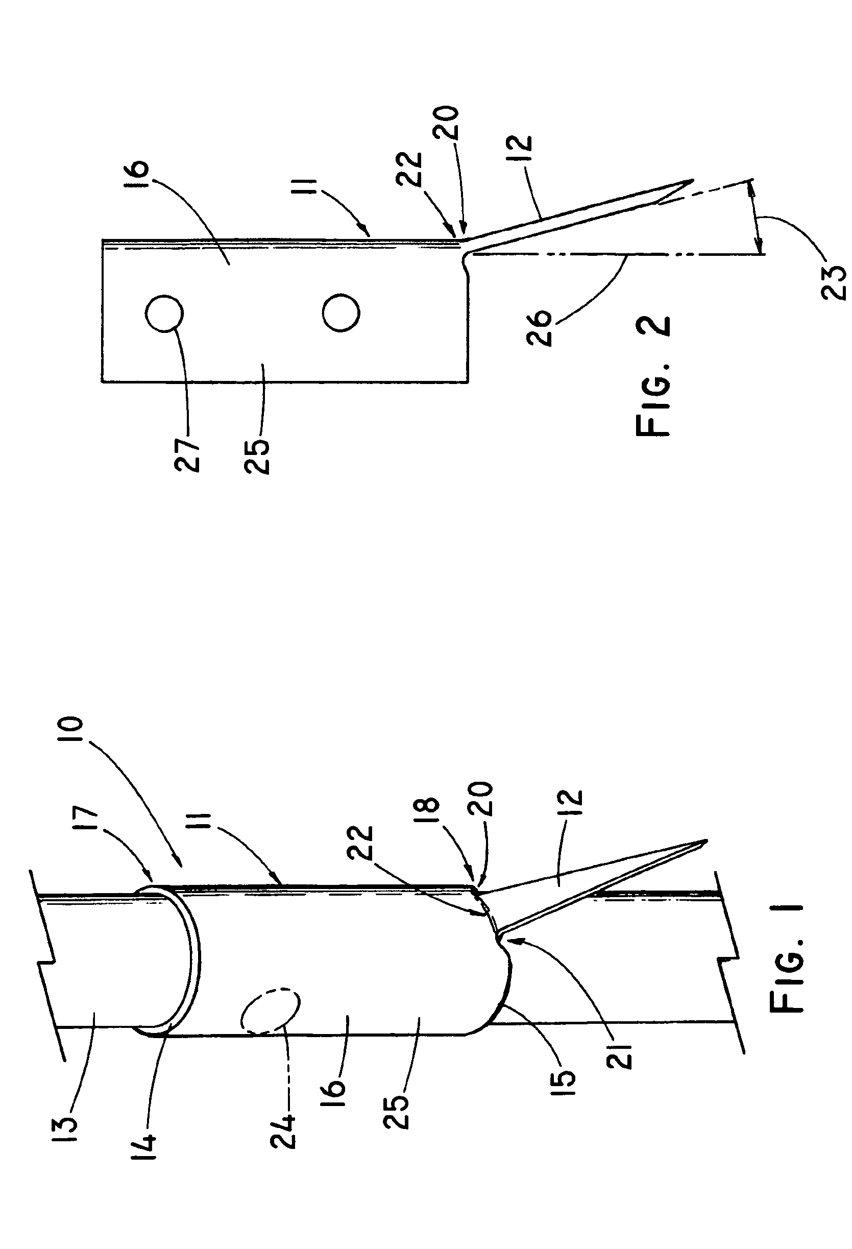
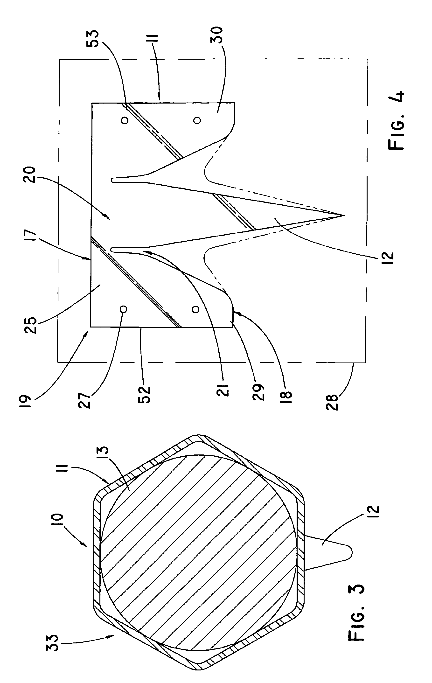
[0025]The present invention, as embodied by FIGS. 1-16, comprises a an intraluminal medical prosthesis 10 that includes an anchoring element 11 having a barb 12 adapted for penetrating tissue to prevent migration of the prosthesis, the anchoring element 11 being formed from a thin layer of material 14, such as a portion of metal cannula 16 or flat sheet of metal 28 (e.g., stainless steel or nitinol) or other suitable material and configured such that the anchoring element 11 at least partially surrounds or encloses at least one strut 13 of the framework of the prosthesis 10, whereby the anchoring element 11 is either fixedly or slidably secured to a strut or elongate member 13 of the support structure or frame of the prosthesis. The configuration of the strut and prosthesis support structure is not particularly critical to the understanding of the invention. It should also be noted that the term ‘cannula’, used herein, is defined to encompass both an anchoring element that is origin...


PUM


Abstract

A medical prosthesis for implantation within the body of a patient comprises a support structure and an anchoring element that comprises a basal portion and at least one barb extending from the basal portion. The anchoring element may be slidably attached to the strut and the strut may include a first stop and a second stop that define a longitudinal zone of movement for the anchoring element. Other devices and methods are described.

Description

CROSS-REFERENCE TO RELATED APPLICATIONS[0001]This application claims priority of provisional application Ser. No. 60 / 539,391, filed Jan. 27, 2004.TECHNICAL FIELD[0002]This invention relates to medical devices, more particularly to intraluminal prostheses such as stents, valves, and the like.BACKGROUND OF THE INVENTION[0003]Prosthetic devices that are delivered intraluminally, such as stents, valves, occluders, shunts, etc., are typically designed to be self expanding or balloon expandable such that they engage the walls of the vessel or duct to become permanently anchored there. To ensure that the prosthesis does not migrate after placement, anchoring barbs are often used that are configured to embed into adjacent tissue and hold the device in place. Barbs are an especially important component of endovascular stent grafts used to exclude an aneurysm sac formed in a blood vessel. For example, the high velocity of blood within the aorta makes it essential to securely anchor the prosth...

Claims


Application Information

Patent Timeline
Patent Type & Authority Patents(United States)
IPC IPC(8): A61F2/06A61F2/01A61F2/02A61F2/82A61F2/86
CPCA61F2/02A61F2/07A61F2/82A61F2/848A61F2/86A61F2002/8483A61F2220/0016
Inventor SISKEN, RICHARD B.CHOULES, BRIAN D.NICKLESS, BENJAMINAGNEW, CHARLES W.
Owner COOK MEDICAL TECH LLC
Why Eureka
Try Eureka