Imaging device-evaluation method, an image correcting method and an imageing device

a technology of image correction and imaging device, which is applied in the direction of instruments, television systems, color signal processing circuits, etc., can solve the problems of deterioration, troublesome quality management, and many imaging apparatuses that cannot obtain images which correctly reflect the brightness of objects on the surfa

Active Publication Date: 2009-08-11
OLYMPUS CORP
View PDF9 Cites 0 Cited by
  • Summary
  • Abstract
  • Description
  • Claims
  • Application Information

AI Technical Summary

Benefits of technology

[0009]It is a first object of the present invention to provide an imaging apparatus evaluation method which correctly evaluates output characteristics of an imaging apparatus without preparing an object surface having a known brightness distribution.
[0010]It is a second object of the present invention to provide an image correction method which obtains an image which correctly reflects an object surface brightness as a corrected image without preparing an object surface having a known brightness distribution.
[0011]It is a third object of the present invention to provide an imaging apparatus which can obtain an image which correctly reflects an object surface brightness without preparing an object surface having a known brightness distribution.

Problems solved by technology

Therefore, many imaging apparatuses cannot obtain images which correctly reflect the object surface brightness.
This standard light emitting surface is required for photography every time, quality management is troublesome, and deterioration occurs.
Therefore, in this type of imaging apparatus, it cannot be said that an evaluation accuracy of output characteristics and a calibration accuracy of images are enough.

Method used


Image

  • Imaging device-evaluation method, an image correcting method and an imageing device
  • Imaging device-evaluation method, an image correcting method and an imageing device
  • Imaging device-evaluation method, an image correcting method and an imageing device

Examples


Embodiment Construction

[0037]Embodiments according to the present invention will now be described hereinafter with reference to the accompanying drawings.

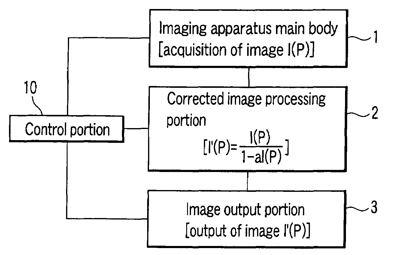
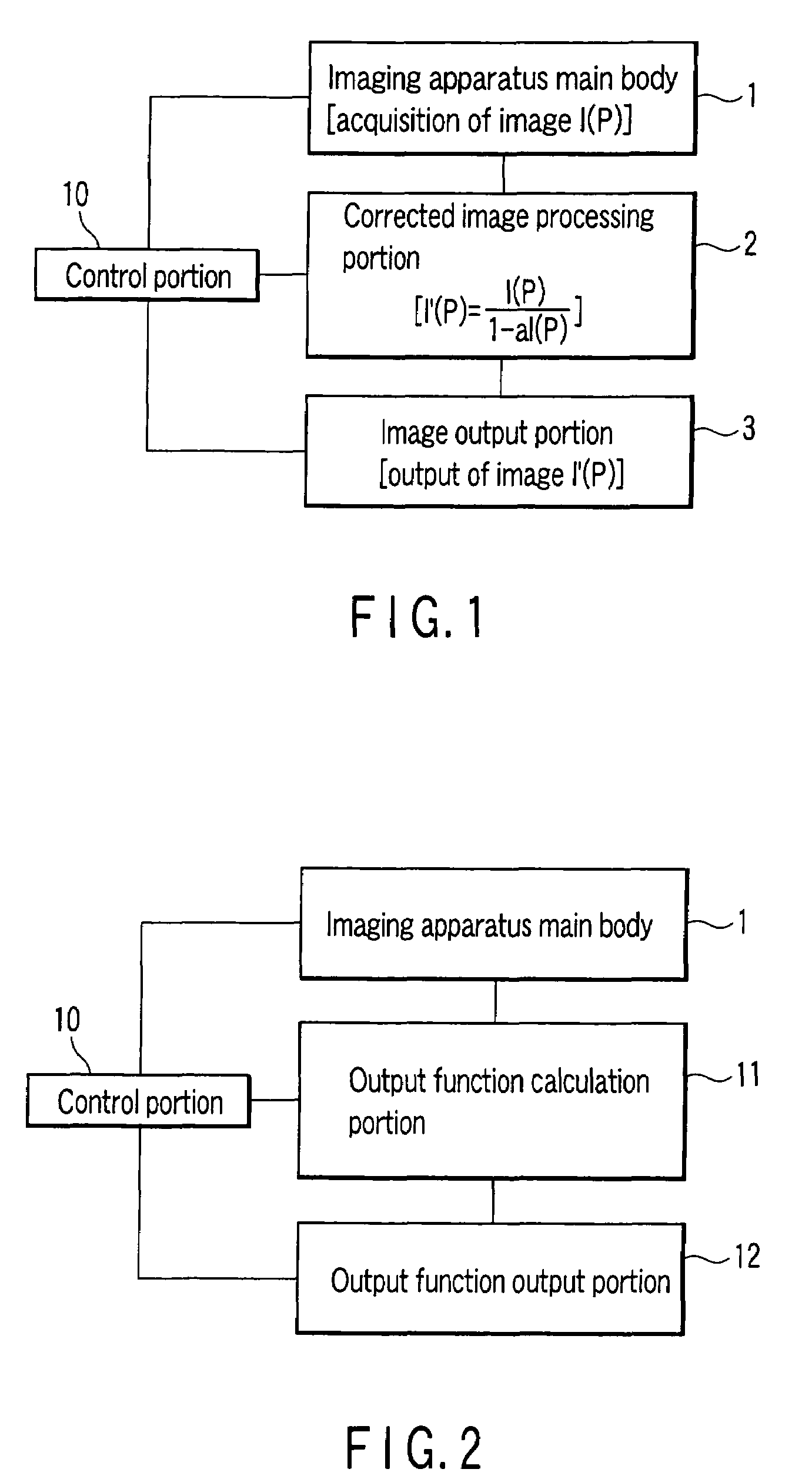
[0038]FIG. 1 is a block diagram of a first imaging apparatus according to an embodiment of the present invention. In FIG. 1, a corrected image processing portion 2 is connected to an imaging apparatus main body 1, and an image output portion 3 is connected to the corrected image processing portion 2. A control portion 10 is connected to the imaging apparatus main body 1, the corrected image processing portion 2 and the image output portion 3. The imaging apparatus main body 1 comprises an imaging element such as a CCD. The corrected image processing portion 2 comprises a computer. The image output portion 3 comprises a memory device. The control portion 10 comprises a CPU.

[0039]The imaging apparatus main body 1 acquires image data I(P). The corrected image processing portion 2 receives the image data I(P), and calculates the following expression, as will...


PUM


Abstract

An imaging apparatus evaluation method of the present invention comprises obtaining an output function of original image data by comparing a plurality of sets of image data which are obtained by imaging the same spatial brightness distribution surface with different exposure times.

Description

CROSS-REFERENCE TO RELATED APPLICATIONS[0001]This is a Continuation Application of PCT Application No. PCT / JP2004 / 005157, filed Apr. 9, 2004, which was published under PCT Article 21(2) in English.[0002]This application is based upon and claims the benefit of priority from prior Japanese Patent Application No. 2003-106978, filed Apr. 10, 2003, the entire contents of which are incorporated herein by reference.BACKGROUND OF THE INVENTION[0003]1. Field of the Invention[0004]The present invention relates to an imaging apparatus evaluation method, an image correction method, and an imaging apparatus.[0005]2. Description of the Related Art[0006]Imaging apparatuses such as a video camera or a digital camera are in heavy usage in general photography, and an output correction such as a dynamic range correction, a visual sensitivity correction or a γ correction is applied to many such imaging apparatuses since a high value is attached to visual characteristics. Therefore, many imaging apparat...

Claims


Application Information

Patent Timeline
Patent Type & Authority Patents(United States)
IPC IPC(8): H04N9/73G06K9/40H04N5/228H04N5/235H04N17/00
CPCH04N17/002
Inventor OKAWA, KANEYASU
Owner OLYMPUS CORP
Why Eureka
Try Eureka