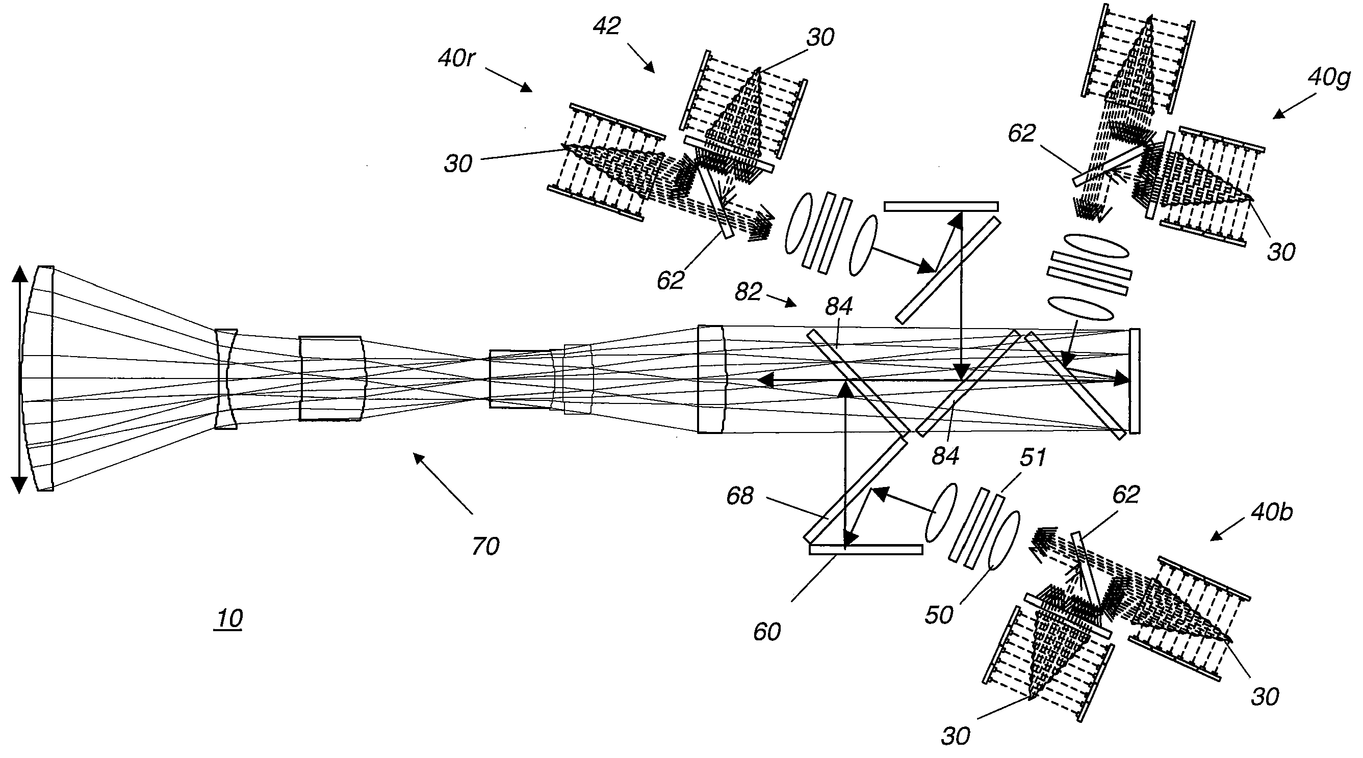
However, there are inherent resolution limitations, with existing devices typically providing no more than 2148×1080 pixels.
In addition, high component and
system costs have limited the suitability of DLP designs for higher-quality digital cinema projection.
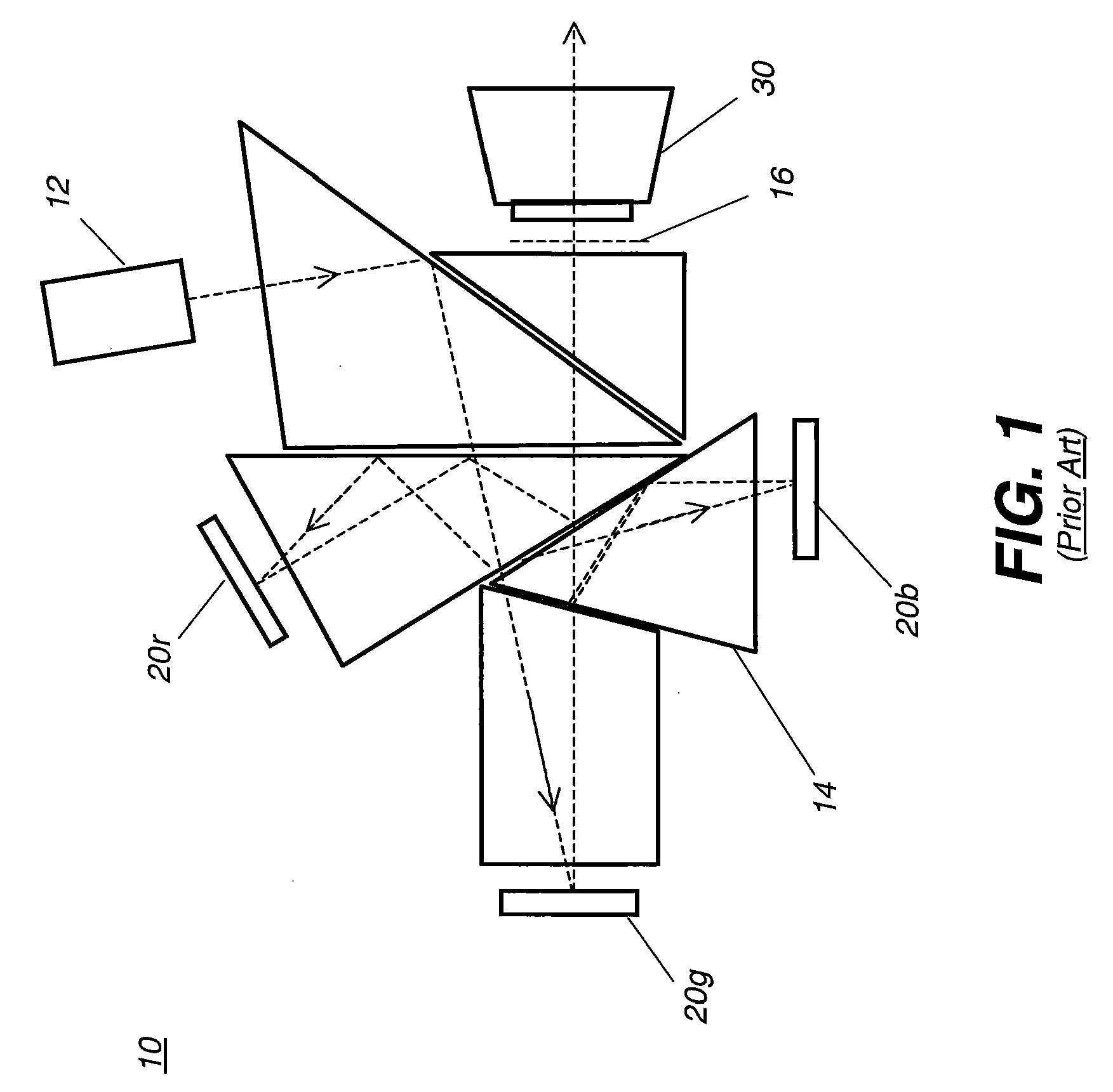
Moreover, the cost, size, weight, and complexity of the Philips or other suitable combining prisms are significant constraints.
In addition, the need for a relatively fast
projection lens with a long working distance, due to brightness requirements, has had a negative
impact on acceptability and
usability of these devices.
However, LCD components have difficulty maintaining the high quality demands of digital cinema, particularly with regard to color, contrast, as the high
thermal load of high brightness projection affects the materials polarization qualities.
It is disadvantaged, however, in that the filter glasses are expensive and the viewing quality can be reduced by
angular shift, head motion, and tilt.
The expensive glasses are also subject to scratch damage and theft causing financial difficulties for the venue owners.
Additionally, adjustment of the
color space can be difficult and there is significant light loss due to filtering, leading to either a higher required lamp output or reduced image brightness.
The
polarizer is required as the DLP is not inherently designed to maintain the polarization of the input light as the window of the device
package depolarizes due to
stress induced bireflingence.
The glasses, however, add expense over embodiments that simply use a
polarizer.
Silvered screens are more costly and exhibit angular sensitivity for
gain.
While this
system is of some value, there is a significant light loss with MEMS (Micro-Electro-Mechanical-
System) based systems since they require polarization, which reduces the output in half.
Similarly, there is additional light loss and added cost from the polarization switcher.
These projectors are, however, commonly more costly due to the difficulty of maintaining high polarization control through
high angle optics.
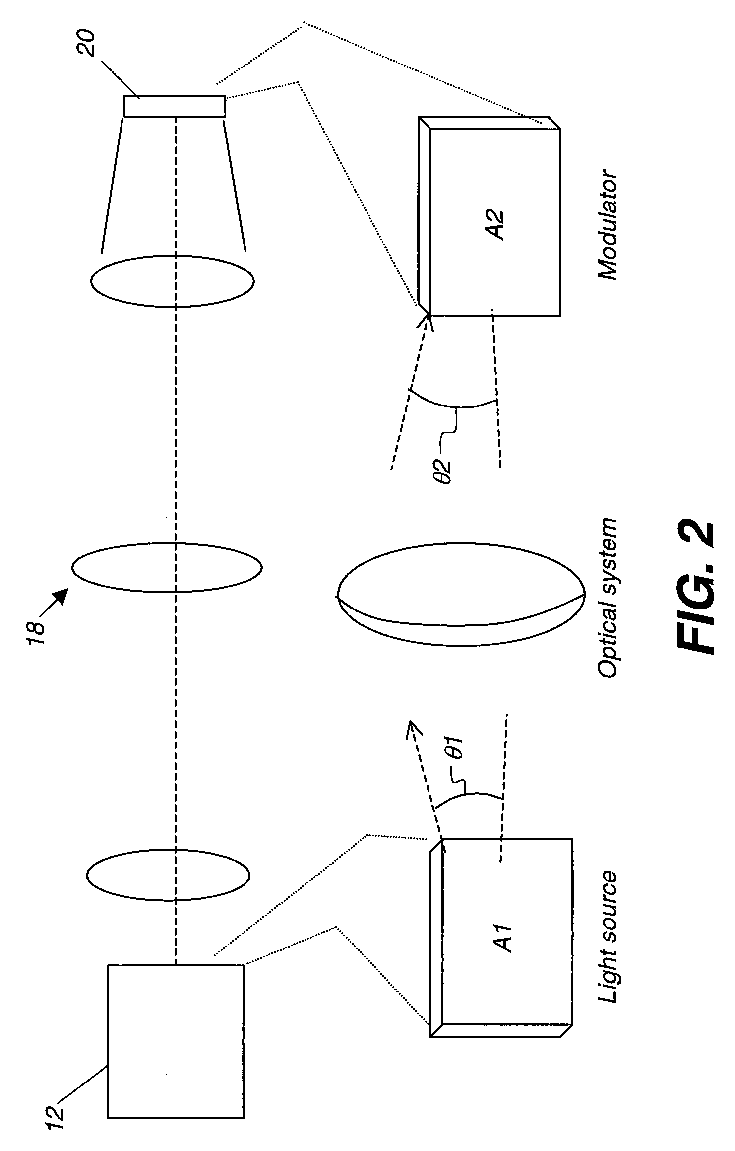
A continuing problem with illumination efficiency relates to etendue or, similarly, to the Lagrange invariant.
Similarly, increasing the
source image size, so that light originates over a larger area, increases etendue.
Typically, however, larger images are more costly.
This is especially true of devices such as LCOS and DLP components, where the
silicon substrate and defect potential increase with size.
As a general rule, increased etendue results in a more complex and costly optical design.
Moreover, although a configuration such as that disclosed in U.S. Pat. No. 5,907,437 handles light from three times the area of the final multicolor image formed, this configuration does not afford any benefit of increased brightness, since each color path contains only one-third of the total
light level.
Poorly matched etendue means that the optical
system is either light starved, unable to provide sufficient light to the spatial light modulators, or inefficient, effectively discarding a substantial portion of the light that is generated for modulation.
LCD-based systems have been compromised by the requirement for polarized light, reducing efficiency and increasing etendue, even where polarization
recovery techniques are used.
DLP device designs, not requiring polarized light, have proven to be somewhat more efficient, but still require expensive, short-lived lamps and costly optical engines, making them too expensive to compete against conventional cinema projection equipment.
Projection apparatus that meet these requirements typically cost in excess of $50,000 each and utilize high wattage
Xenon arc lamps that need replacement at intervals between 500-2000 hours, with typical replacement cost often exceeding $1000.
The large etendue of the
Xenon lamp has considerable
impact on cost and complexity, since it necessitates relatively fast
optics to collect and project light from these sources.
One drawback common to both DLP and LCOS LCD spatial light modulators (SLM) has been their limited ability to use
solid-state light sources, particularly
laser sources.
Solid-state lasers promise improvements in etendue,
longevity, and overall spectral and brightness stability but, until recently, have not been able to deliver visible light at sufficient levels and at costs acceptable for digital cinema.
However, brightness itself is not yet high enough; the combined light from as many as 9 individual arrays is needed in order to provide the necessary brightness for each color.
There are difficulties with each of these types of solutions.
In a high lumen
projector, however, this approach presents a number of difficulties.
Manufacturing yields drop as the number of devices increases and heat problems can be significant with larger scale arrays.
Coherence can also create problems for monolithic designs.
Coherence of the
laser sources typically causes artifacts such as optical interference and speckle.
In addition, reducing the spatial and temporal coherence at the source is preferred, as most means of reducing this incoherence beyond the source utilizes components such as diffusers that increase the effective extent of the source (etendue), cause additional light loss, and add expense to the system.
However, conventional solutions using these devices have been prone to a number of problems.
One limitation relates to device yields.
Due largely to heat and packaging problems for critical components, the commercialized VECSEL array is extended in length, but limited in height; typically, a VECSEL array has only two rows of emitting sources.
The use of more than two rows tends to dramatically increase yield and packaging difficulties.
This practical limitation would make it difficult to provide a VECSEL illumination system for projection apparatus as described in the Glenn '145 disclosure, for example.
Although Kruschwitz et al '454 and others describe the use of
laser arrays using organic VCSELs, these organic lasers have not yet been successfully commercialized.
In addition to these problems, conventional VECSEL designs are prone to difficulties with power connection and heat sinking.
Thus, there can be significant current requirements and
heat load from the unused current.
Coupling of the laser sources to the
projection system presents another difficulty that is not adequately addressed using conventional approaches.
However, these are more difficult to
package in array form and traditionally have a shorter lifetime at higher brightness levels.
Conventional solutions do not adequately address the problems of etendue-matching of the laser sources to the system and of thermally separating the illumination sources from the optical engine.
Moreover, conventional solutions do not address ways to effectively utilize lasers effectively to generate stereoscopic digital cinema projection systems.


