Planar light source device having polarization separator formed of two sheets with mating triangular prisms and different indices of refraction

a technology of polarization separator and light source device, which is applied in the direction of polarizing elements, lighting and heating apparatus, instruments, etc., can solve the problems of insufficient light utilization efficiency, difficult to make the incident light orthogonal, and not true that 100% of the emitted ligh

Inactive Publication Date: 2001-05-29
SEKISUI CHEM CO LTD +1
View PDF14 Cites 248 Cited by
  • Summary
  • Abstract
  • Description
  • Claims
  • Application Information

AI Technical Summary

Problems solved by technology

However, it is not true that 100% of the emitted light from a back light was actually emitted to a person who observes the display surface.
It is essential to this device that the light emitted out of the light guide is incident orthogonally to the prism array so that the utilization efficiency of the light is not sufficient when the light passes the dispersing sheet placed between the light guide and the prism array because it is difficult to make the light inci

Method used


Image

  • Planar light source device having polarization separator formed of two sheets with mating triangular prisms and different indices of refraction
  • Planar light source device having polarization separator formed of two sheets with mating triangular prisms and different indices of refraction
  • Planar light source device having polarization separator formed of two sheets with mating triangular prisms and different indices of refraction

Examples


first embodiment

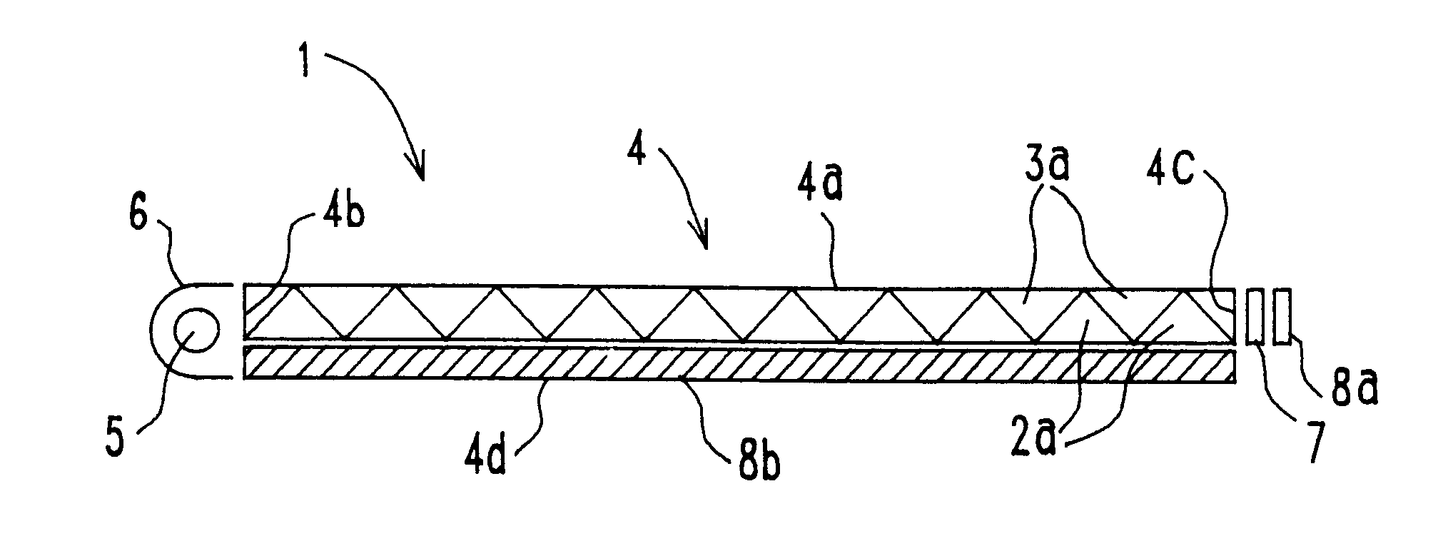
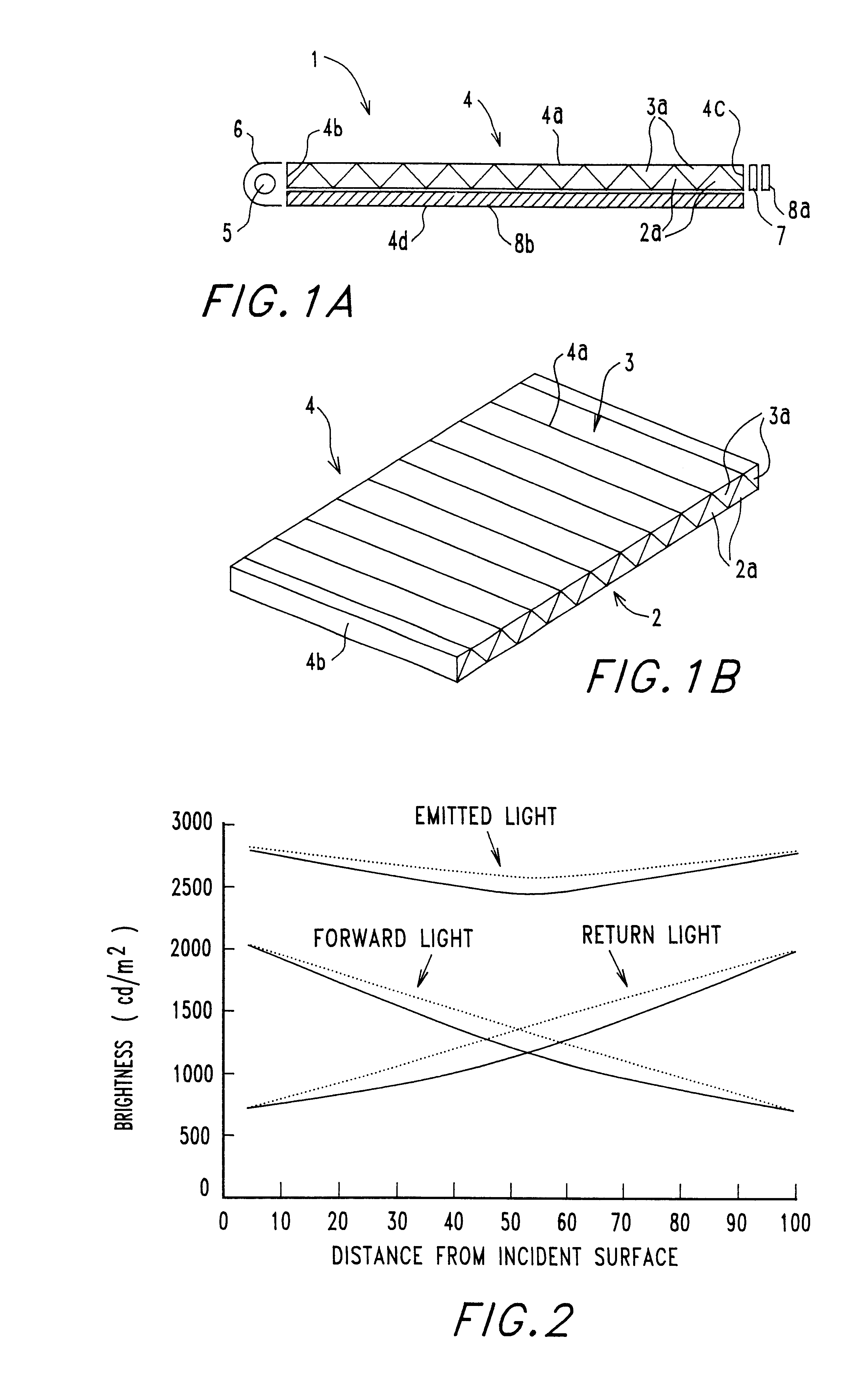
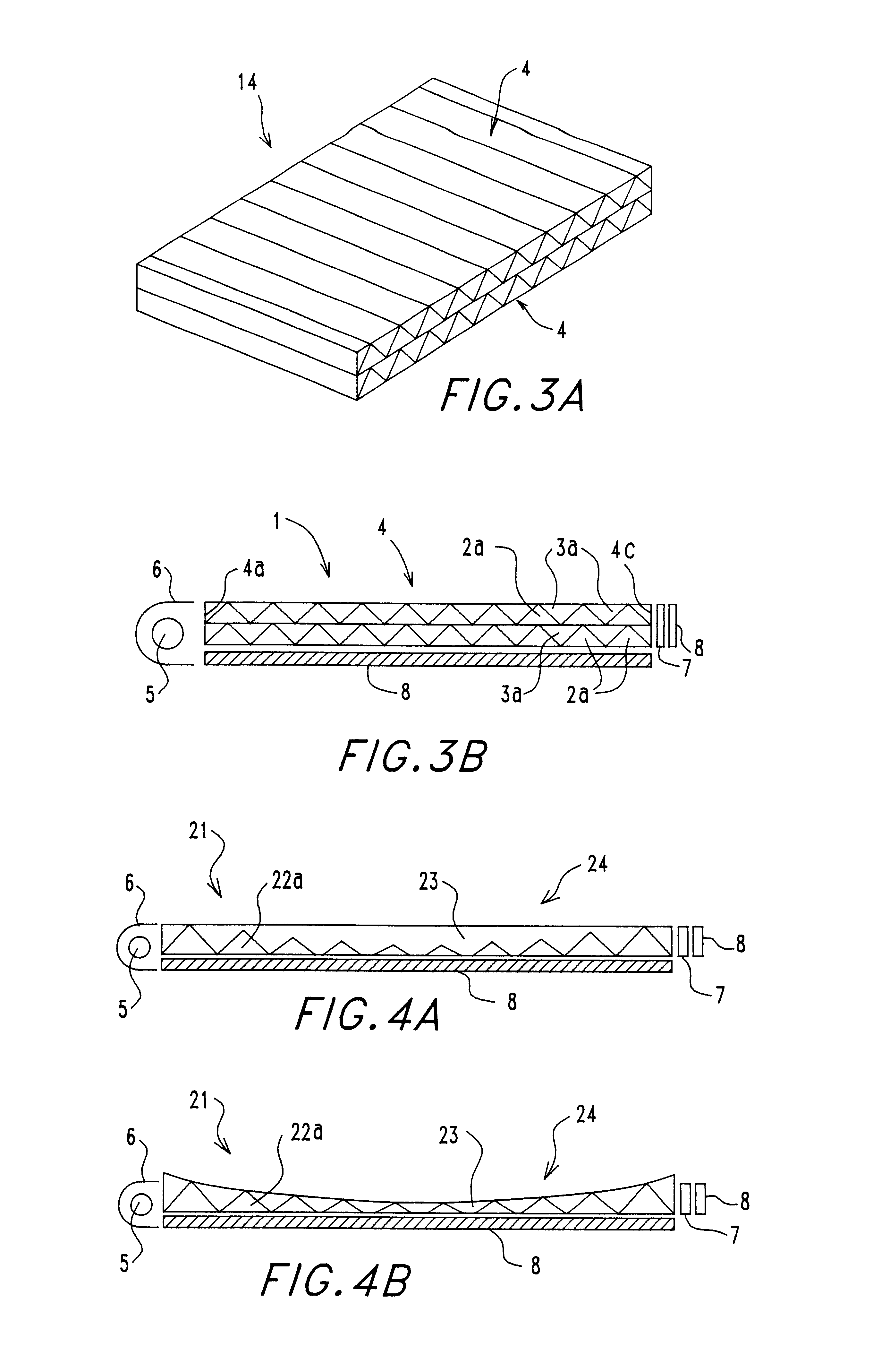
FIG. 1 shows a schematic diagram of a basic plane light source device 1 of this invention (the first embodiment). In FIG. 1, a fluorescent lump 5 is generally used as the light source. The fluorescent lump 5 has a function to emit a light to the incident surface 4b of the light guide 4 which is the (b) polarization separator means.

A lump reflector 6 is positioned at the side of the fluorescent lump 5 opposite to the light guide 4. The lump reflector 6 prevents the light from the fluorescent lump 5 from scattering to the directions other than the light guide 4.

The light guide 4 of this invention functions as (b) polarization separator means. The polarization separation function is provided by using the principle of Brewster angle. The Brewster angle as used herein is an angle between the direction of an incident light and the normal to the media interface when the intensity of reflection of P component is zero, when the light is incident at a given angle to the interface of two mater...

embodiment 1

A light collecting member is not shown in FIG. 1(A) which relates to the However, it is recommendable to place a light collecting member between the light source 5 and the light guide 4 to reduce the divergence of the incident angle of the light from the light source. This is for the purpose of collimating the light vector preferably to a same direction because a fluorescent lump is a linear light source which emits diffused light. If the direction of incidence to the light guide is not uniform, the polarization split function is not obtained with a sufficient efficiency due to the diverted angle of the incident light even if the angle of the two media is precisely adjusted to an angle which meets Brewster angle relative to the light coming from the direction which is in right angle to the incident surface of the light guide. It is preferable that the light collection means is typically one or more transparent resin sheets having a ridged surface placed between the fluorescent lump...

embodiment 2

In the embodiment 2, one which is of a similar shape is prepared with different materials. That is, a light guide similar to the embodiment 1 is utilized in the plane light source except that the sheet material 2 was made from a transparent acrylic resin (index of refraction n=1.49) while the sheet material 3 was made from a transparent photo setting resin compound (index of refraction n=1.58) of triaryl isocyanate and thiol components, and the cross sectional shape of the triangular column of the array is a right angled isosceles triangle having 3 edges of 2 mm, 2 mm and 2 mm lengths.


PUM


Abstract

The purpose of the invention is to provide a light guide of a variety of forms having a uniform distribution of brightness in the plane and a planer light source device for a liquid crystal display device which uses such light guide. The light guide comprises a first surface which is a surface to which a natural polarization light is incident and a second surface other than the first surface which is an exit surface of a specific polarization light into which, said natural polarization light is modulated, wherein;said light guide has an interface of two materials of different indices of refraction oriented at an angle of thetaB+/-alpha degrees relative to the primary propagation direction of said incident light, said thetaB being an angle satisfying Brewster's condition, more than two orientations of said interface exist in a single light guide, and the difference between the indices of refraction of the two materials of different indices of refraction is between 0.001 and 1.0. thetaB is typically about 45 degrees. The light guide comprises a first transparent member having a plurality of upwardly convex right angle isosceles triangles on a first surface thereof and a first index of refraction and a second transparent member having a plurality of downwardly convex right angle isosceles triangles on a second surface thereof and a second index of refraction, and said first surface and said second surface contact each other.

Description

TECHNOLOGICAL AREAThis invention relates to a plane light source device which emits light uniformly from a plane having a given area using a light source of unpolarized light (natural light) like a light from a fluorescent lump, and an optical guide used for such light source device. The plane light source device and the optical guide are typically incorporated in a back light module of a liquid crystal display device.BACKGROUND TECHNOLOGYA plane light source device in the prior art has been so designed that an emitting light is bright and comfortably perceived by an observer because it was dispersed and collected by means of an optical dispersing sheet or a prism sheet.However, it is not true that 100% of the emitted light from a back light was actually emitted to a person who observes the display surface. Particularly, a polarizer allows only one of orthogonal P and S components to pass it while inhibiting the other component by absorbing it so that about 50% of the light is lost....

Claims


Application Information

Patent Timeline
IPC IPC(8): F21V8/00G02F1/1335G02F1/13G02B6/00G02F1/13357
CPCG02B6/0056G02F1/13362G02B6/0001G02B6/0038G02B6/0053G02B6/0055G02F1/133536G02F2001/13355G02F1/13355
Inventor HATAZAWA, TSUYONOBUHAYASHI, HIDEKINAKAMURA, KOZOWATANABE, TAKASHIMAMIYA, JOHJISUZUKI, MASARUTANASE, HIROSHI
Owner SEKISUI CHEM CO LTD
Why Eureka
Try Eureka