Modular frame connector system

a technology of modular frame and connector system, which is applied in the direction of girders, joists, buildings, etc., can solve the problems of difficult adjustment of frames that are nailed or bolted together, special problems of modular construction, and difficulty in adjusting frames

Active Publication Date: 2009-08-25
JENKINS JOSEPH W
View PDF26 Cites 27 Cited by
  • Summary
  • Abstract
  • Description
  • Claims
  • Application Information

AI Technical Summary

Problems solved by technology

Nailing or bolting a structural frame together requires considerable skill.
Frames that are nailed or bolted may not be adjusted easily after assembly to accommodate shifting foundations or misalignments.
Modular construction, however, presents special problems.
Components made from lumber may be difficult to standardize.
Since lumber takes years to produce, it may fluctuate in price.

Method used


Image

  • Modular frame connector system
  • Modular frame connector system
  • Modular frame connector system

Examples


first embodiment

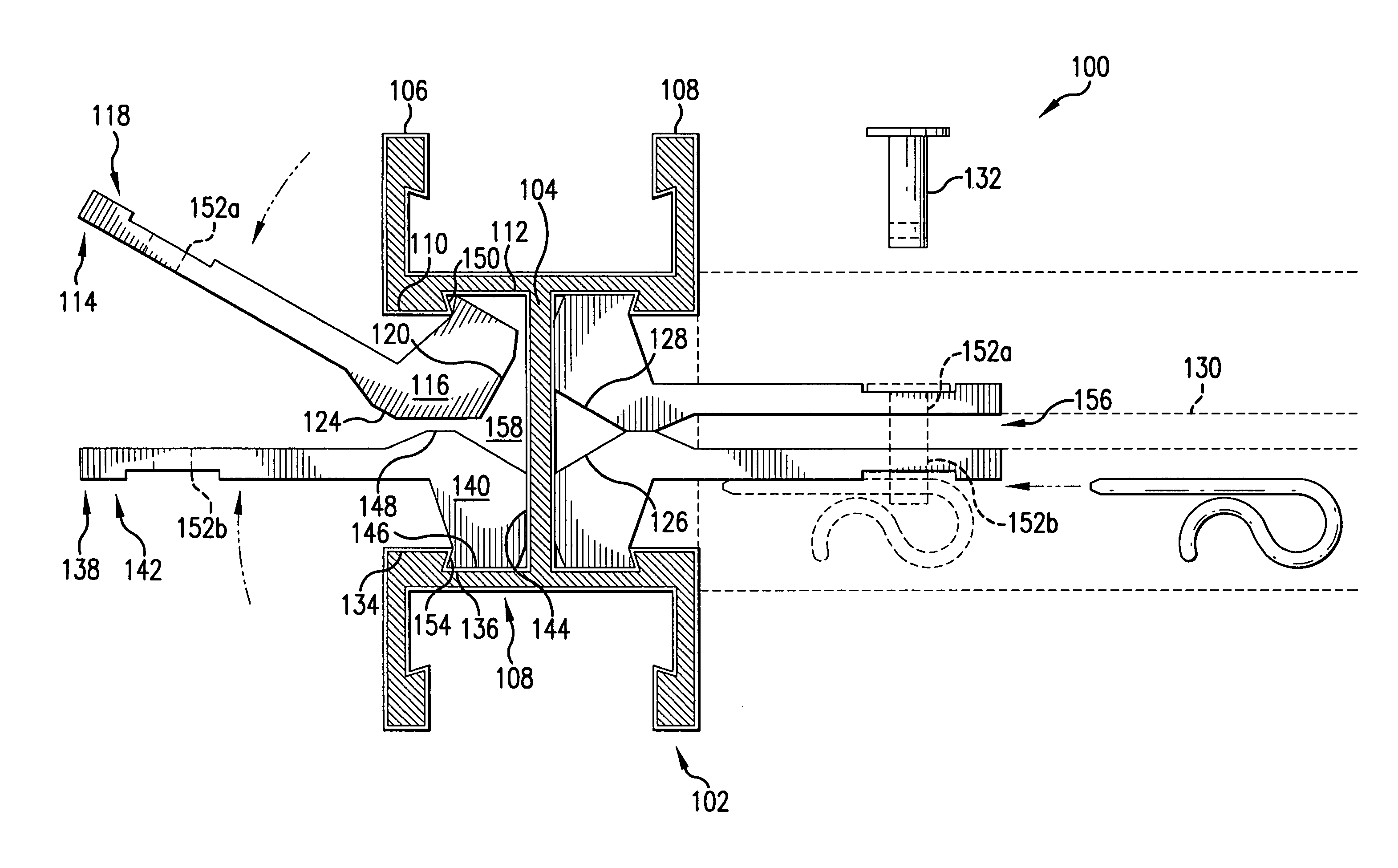
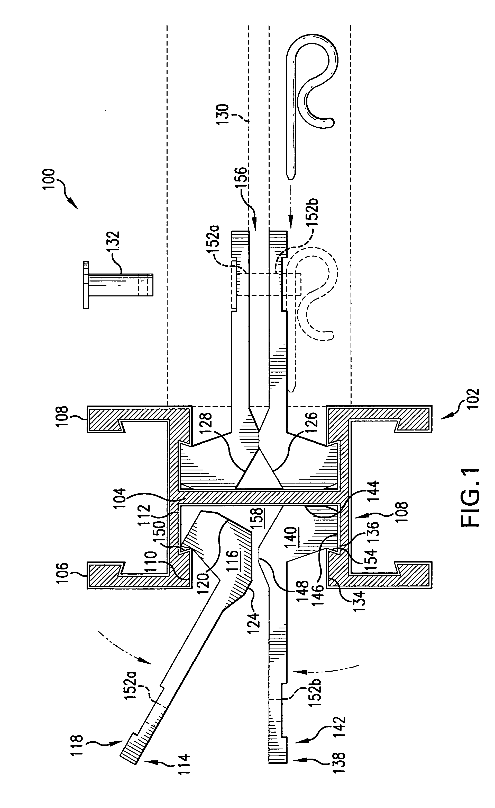
[0026]In FIG. 1 is shown a modular frame connector system 100 according to the present invention. Modular frame connector system 100 may include a beam, stanchion, column, pillar, or post 102 having a web 104 and a front and rear flanges 106 and 108 which are disposed fixedly on web 104. The designations “front” and “rear” as used herein are merely convenient labels for various elements and are not intended to imply any particular physical orientation or order of installation.

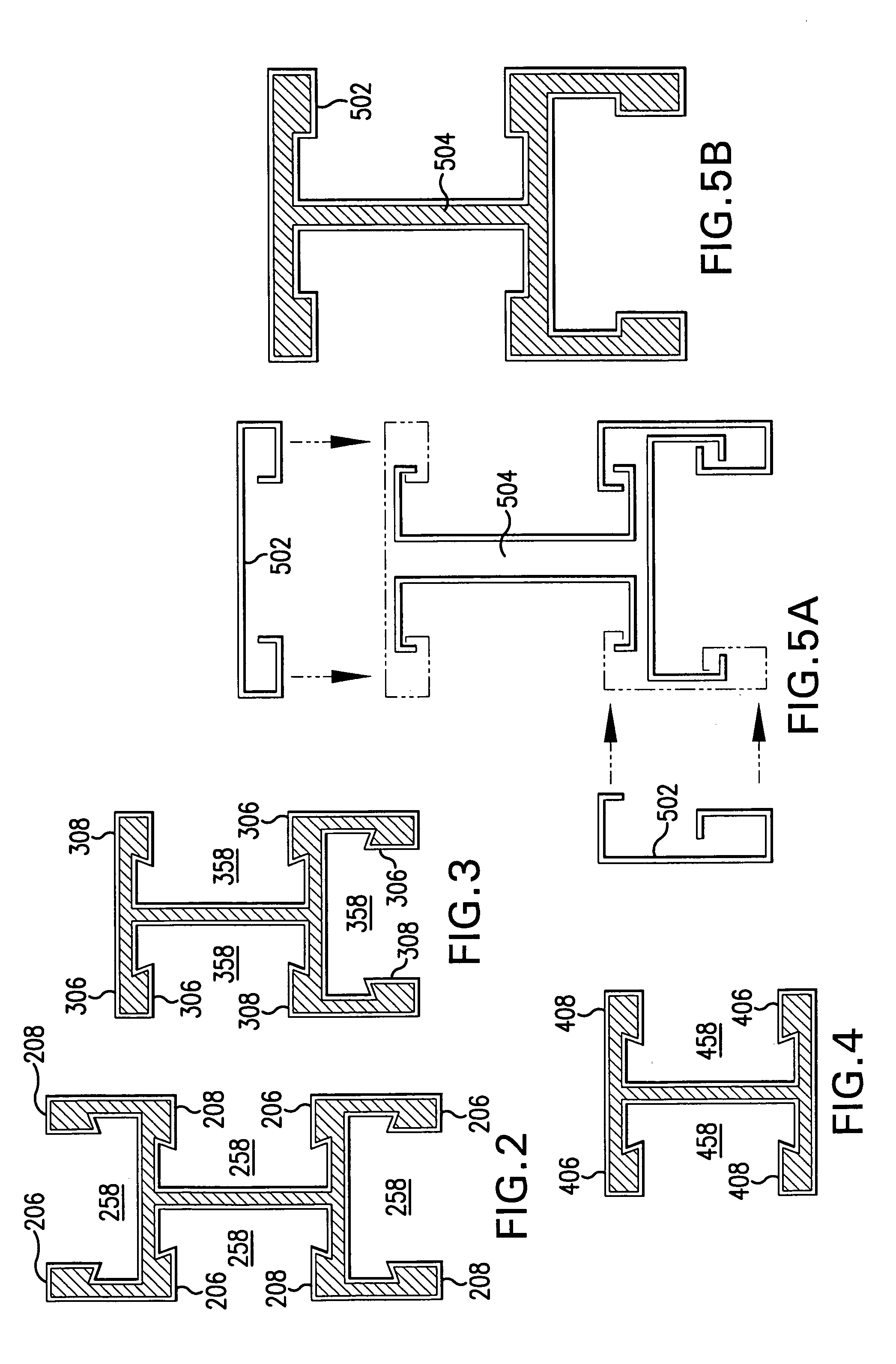
[0027]In several embodiments, post 102 may be similar to an I-beam or a W-beam, such as a modified wide flange beam as shown in FIG. 1. This profile and others shown in FIGS. 2-4, 5D and 5F may be used as a post, beam or rafter. In several embodiments, post 102 may have a skin made of a brake-formed or extruded metal substantially resistant to oxidation, such as aluminum. The skin may also be made of a coated cold- or hot-rolled steel, such as galvanized steel. Post 102 may have either no core at all, as shown ...

second embodiment

[0047]In the invention, illustrated in FIG. 6, one or more fastening plates 614 may be used. This embodiment may be referred to as a type “B” fastener. This embodiment may be used with a structural member 630 that has been rotated 90° with respect to a channel 658, as may be the case for joists, purlins or certain wall conditions such as ties. Aperture 652 in fastening plate 614 may flank structural member 630. Fastener 632 may be inserted through aperture 652 and structural member 630. More than one fastener 632 may be used.

[0048]In one embodiment, structural member 630 may be disposed proximate to a pierced end 618. In one embodiment, a fastener may be disposed pierceably through aperture 652 and structural member 630. In one embodiment, the fastener is any suitable fastening device such as, for example, a pin, a bolt, a rivet, or a spike. In several embodiments, structural member 630 is a second post, a beam, a joist, a stud, a panel, or a fastener.

[0049]In one embodiment, a post...


PUM


Abstract

A modular frame connection is formed by abutting a front camming surface of a front camming end of a front fastening plate against a rear camming surface of a rear camming end of a rear fastening plate while a front pierced end of the front fastening plate and rear pierced end of the rear fastening plate are separated, inserting the front and rear camming ends between a front and rear flanges of a post or beam, rotating the front pierced end toward the rear pierced end until a front finger surface of the front camming end is disposed insertably between a front lip of the front flange and a web of the post or beam and abutably to the front flange and a front abutment surface substantially orthogonal to the front fastening plate is disposed abutably to the web, rotating the rear pierced end toward the front pierced end until a rear finger surface of the rear camming end is disposed insertably between a rear lip of the rear flange and the web of the post or beam and abutably to the rear flange and a rear abutment surface substantially orthogonal to the rear fastening plate is disposed abutably to the web.

Description

BACKGROUND OF THE INVENTION[0001]1. Field of the Invention[0002]The invention relates to modular frame connectors, such as those that might be used for connecting structural framing, and framing structures utilizing the modular frame connectors.[0003]2. Description of the Related Art[0004]Structures such as houses have been built traditionally with roofs and walls supported by frames made of lumber. The frames are often secured by nails or bolts. Nailing or bolting a structural frame together requires considerable skill. Frames that are nailed or bolted may not be adjusted easily after assembly to accommodate shifting foundations or misalignments. It would be desirable if a frame connection were quickly and easily made. It would be desirable if a location of a frame connection were adjustable after connection. It would be desirable for future additions to the structure to be easily attached. It would be desirable for all elements of the structure to be easily de-mountable so that th...

Claims


Application Information

Patent Timeline
Patent Type & Authority Patents(United States)
IPC IPC(8): E04H12/00E04B1/61E04C3/00E04B1/24E04B7/02E04B7/04E04C3/04E04C3/29
CPCE04B1/24E04B7/024E04B7/04E04C3/29E04B2001/2415E04B2001/2433E04B2001/2448E04C2003/0473E04B2001/2481E04B2001/2484E04B2001/249E04C2003/0452E04B2001/2475
Inventor JENKINS, JOSEPH W.
Owner JENKINS JOSEPH W
Why Eureka
Try Eureka