
Light emitting and receiving device

a light emitting and receiving device technology, applied in the field of light emitting and receiving devices, can solve the problems of limited prior art devices, unsuitable devices adapted to a first application, and generally unsuitable where a focused light source is used

Active Publication Date: 2009-09-01
9609385 CANADA INC
View PDF4 Cites 53 Cited by
  • Summary
  • Abstract
  • Description
  • Claims
  • Application Information

AI Technical Summary

Problems solved by technology

Typically, such prior art devices are limited to one of two general applications: a first application such as a flashlight where the light source is focused, intensified and collimated along a general axis; and a second application such as a safety beacon where the light source is diffused such that the device is visible from a variety of directions.
One drawback of such prior art devices is that a device adapted to a first application is unsuitable for the other application, that is flashlights and the like generally do not make good beacons and beacons and the like are generally unsuitable where a focused light source is required.
However such diffusers constitute an additional piece or part which must be attached to the flashlight, typically absorb a fair amount of the light generated by the light source and are still not visible over a sufficiently wide angle to be suitable for many applications where a safety beacon or the like is called for.

Method used


Image

  • Light emitting and receiving device
  • Light emitting and receiving device
  • Light emitting and receiving device

Examples


Embodiment Construction

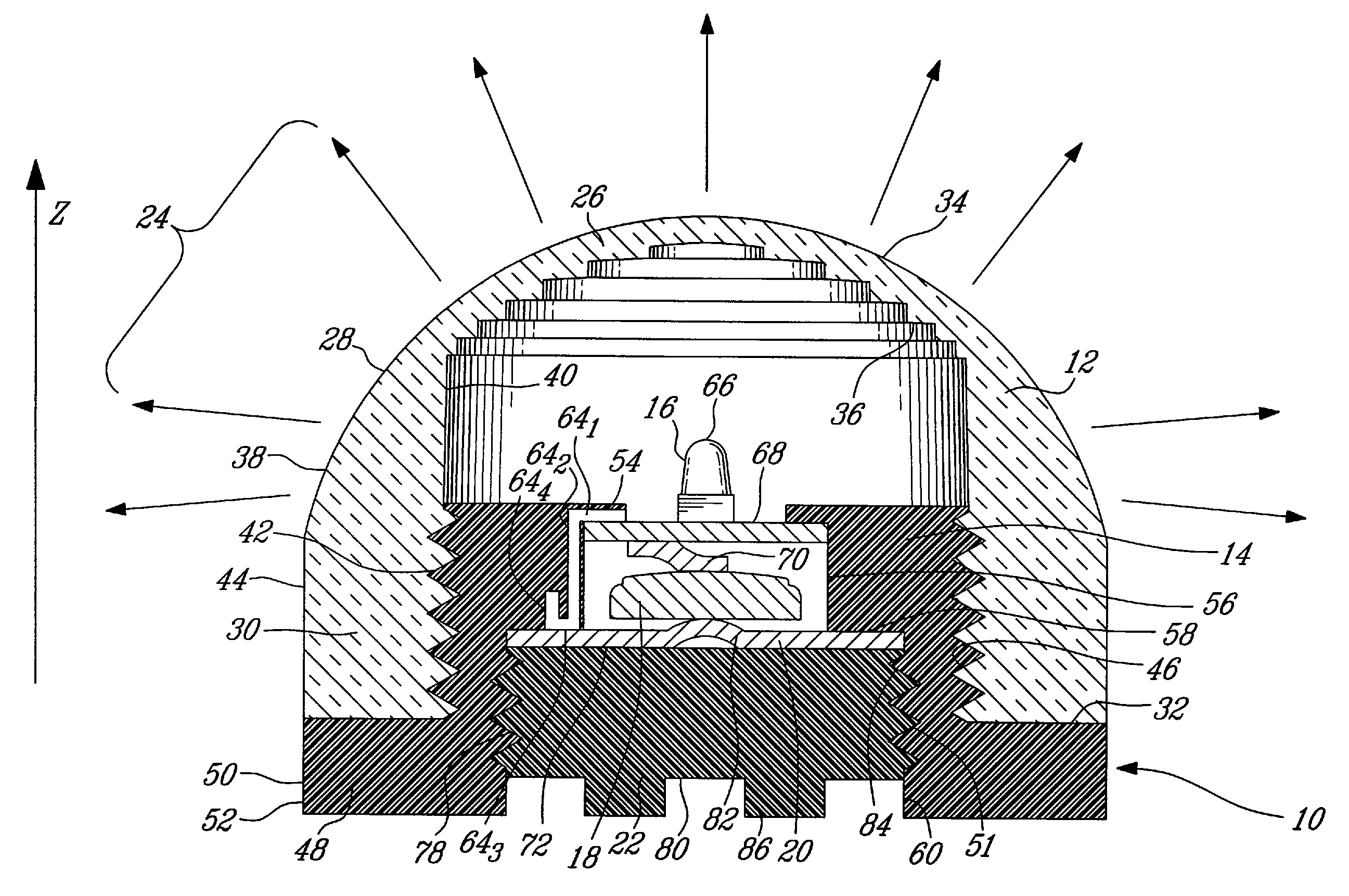
[0025]Before proceeding with a detailed description of an illustrative embodiment of the present invention, it is important to first discuss certain principles in projection optics that are important to fully implement the following. Specifically, the use of stepped-surface and Fresnel-type lenses in conjunction with an axially movable light source is of particular importance.

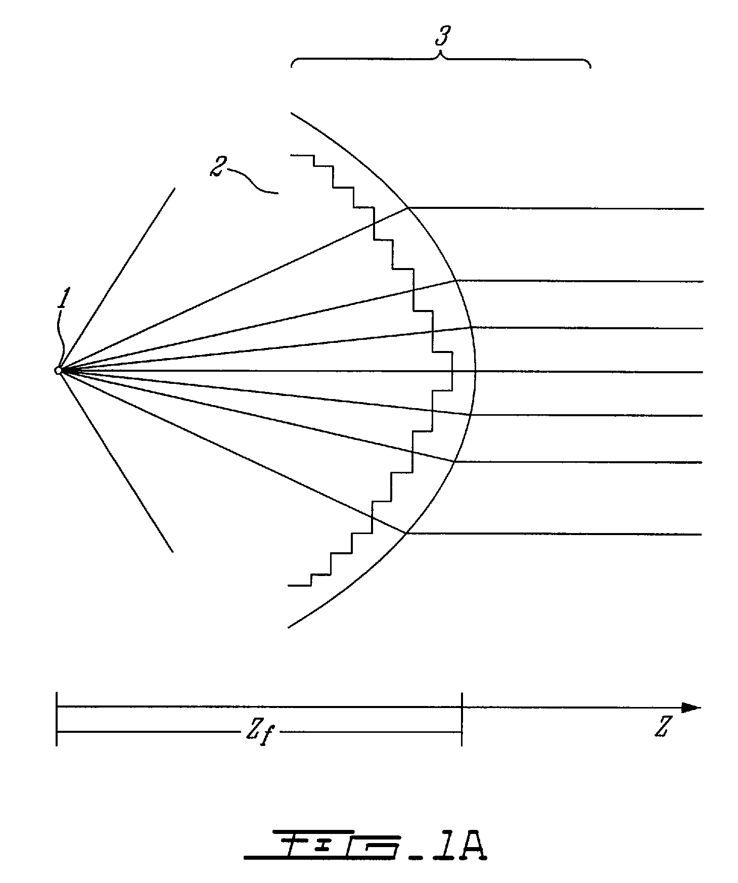
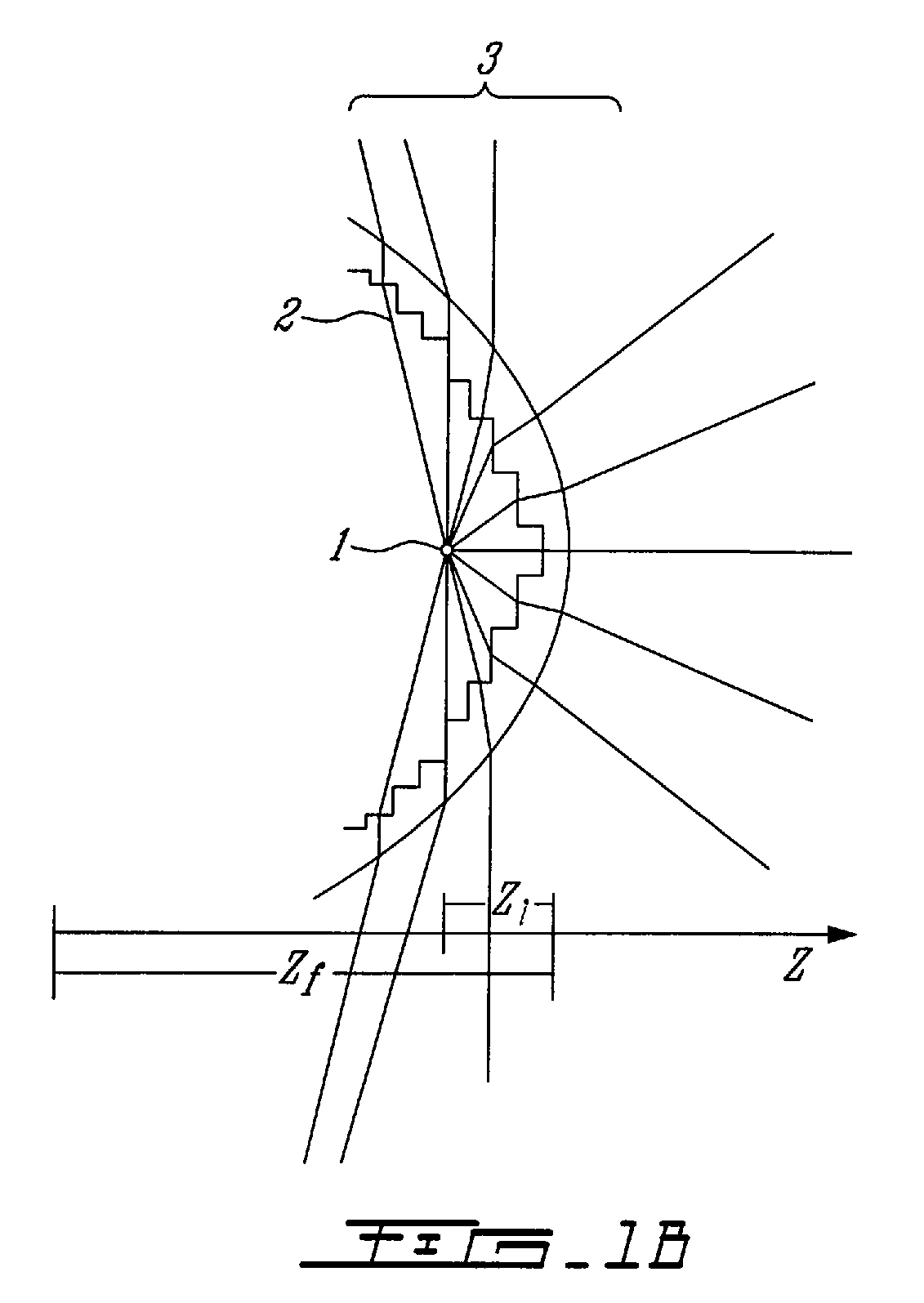
[0026]Referring first to FIG. 1A, and in accordance with an illustrative embodiment of the present invention, an approximated point light source 1 is positioned behind the concave face 2 of a generally spherical or rounded stepped-surface lens 3 at a distance Zf, along the optical axis of the lens, approximately equal to the focal length of the lens. Basic geometrical optics in this scenario prescribes that the light refracted by the lens will be collimated on output and be projected directionally outward with minimal divergence. In FIG. 1B, the light source 1 is again positioned behind concave face 2 of the st...


PUM


Abstract

There is disclosed an adjustable light emitting device for selectively projecting light directionally and omnidirectionally, the device comprising a stepped surface lens having a focal point and a light source positioned substantially along an optical axis of the lens and adapted for movement along the axis between the focal point and the lens. There is also disclosed a light emitting device comprising a partially collimated light source and a lens. When light emitted by the light source passing through the lens is simultaneously projected in an arc of at least 180° and further wherein a measured intensity of the projected light within the arc is at least one half of a maximum intensity of the emitted light. Both devices may also include a light sensor, or the light sensor may be included together with the lens in a separate package for use in light sensing applications.

Description

CROSS REFERENCE TO RELATED APPLICATIONS[0001]This application claims priority on U.S. provisional application No. 60 / 771,877, filed on Feb. 10, 2006 the entirety of which is incorporated herein by reference.FIELD OF THE INVENTION[0002]The present invention relates to a light emitting and receiving device. In particular, the present invention relates to a device comprising a light source and / or light sensor and an adjustable lens for use in combination with the light source and / or light sensor.BACKGROUND TO THE INVENTION[0003]The prior art discloses a variety of portable devices for emitting light comprising one or more light sources and a lens or other means for focusing or diffusing the light. Typically, such prior art devices are limited to one of two general applications: a first application such as a flashlight where the light source is focused, intensified and collimated along a general axis; and a second application such as a safety beacon where the light source is diffused su...

Claims


Application Information

Patent Timeline
Patent Type & Authority Patents(United States)
IPC IPC(8): F21V5/00
CPCF21V14/06F21V23/0442F21S9/02F21V5/045F21Y2101/02F21V31/005F21V17/12F21Y2115/10G01J1/0266G01J1/0411G01J1/0448
Inventor FORD, TIMOTHY D. F.
Owner 9609385 CANADA INC
Learn More