
Locating and tracking acoustic sources with microphone arrays

Inactive Publication Date: 2009-09-01
MITSUBISHI ELECTRIC RES LAB INC
View PDF2 Cites 21 Cited by
  • Summary
  • Abstract
  • Description
  • Claims
  • Application Information

AI Technical Summary

Problems solved by technology

Spurious reflections of the signals and microphone inconsistencies do not pose a practical issue because these are ‘learned’ as part of the training process.

Method used


Image

  • Locating and tracking acoustic sources with microphone arrays
  • Locating and tracking acoustic sources with microphone arrays
  • Locating and tracking acoustic sources with microphone arrays

Examples


Embodiment Construction

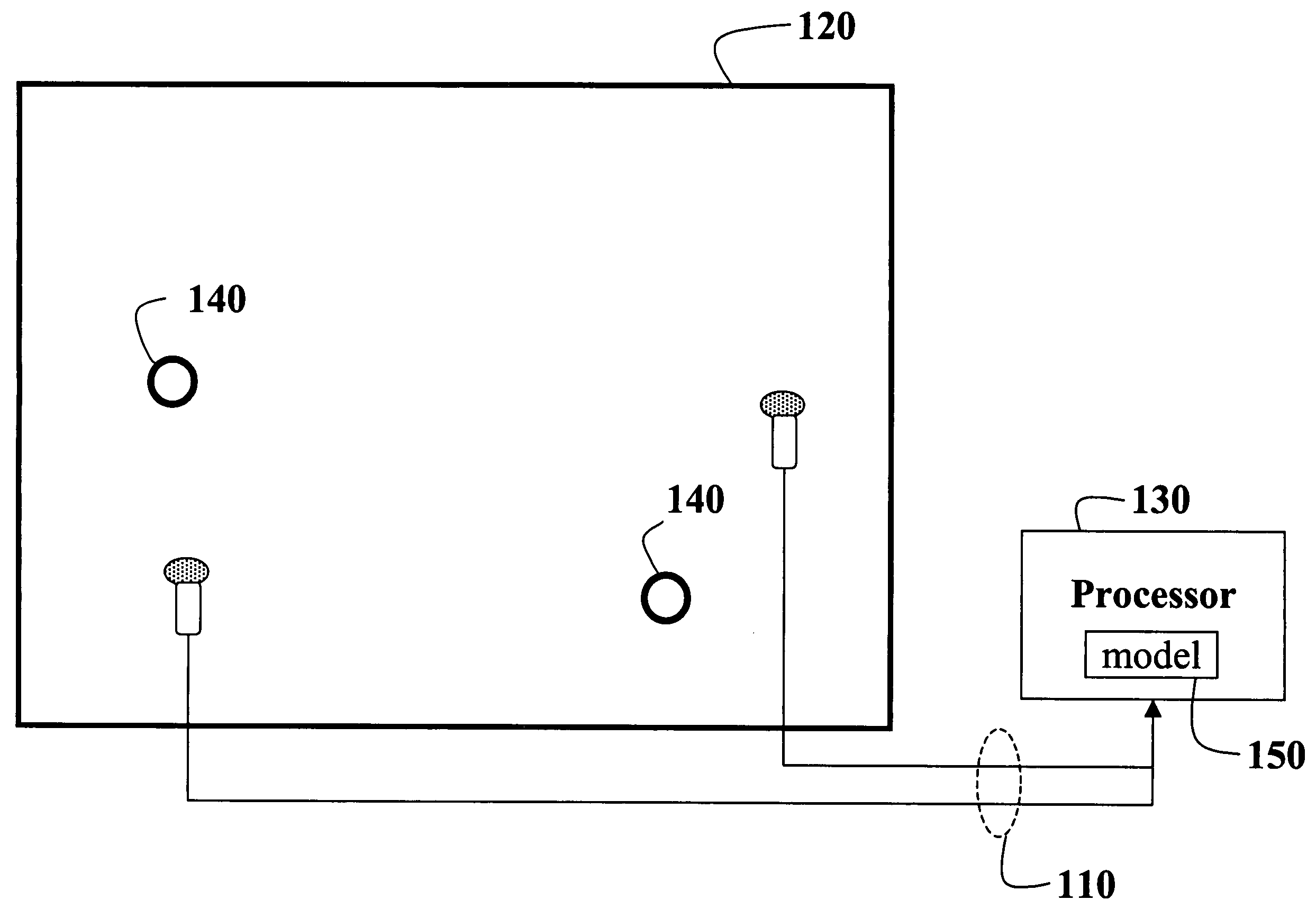
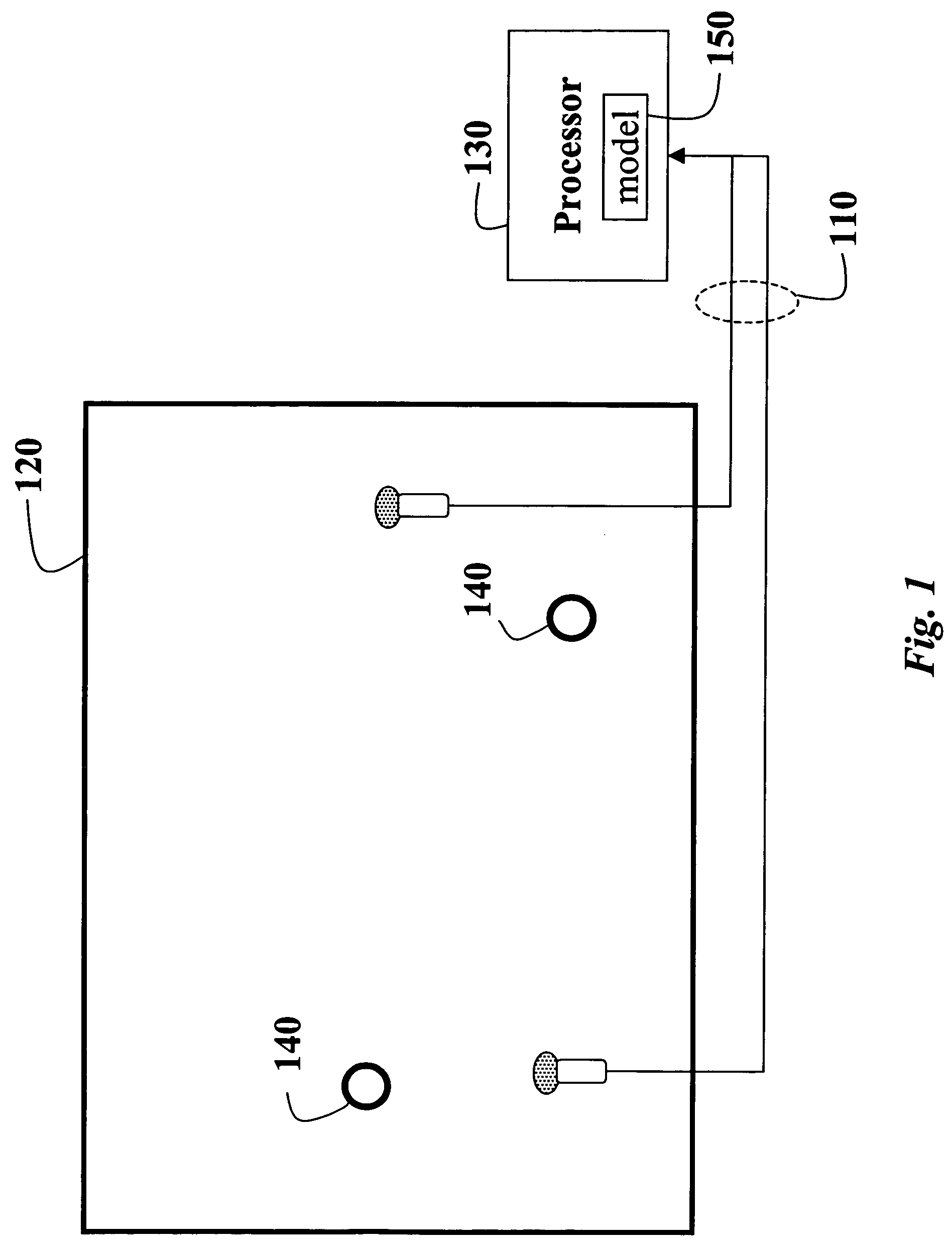
[0019]FIG. 1 shows a system for locating and tracking acoustic sources according to our invention. An array of microphones 110 is placed in an acoustic environment 120. The microphones are fixed in place at unknown positions, and the microphones have unknown response characteristics. The microphones are connected to a processor 130. The environment also includes one or more acoustic sources 140 at unknown locations, used for training. The sources can also move along unknown trajectories. The sources produce ‘training’ signals.

[0020]For simplicity, we describe the case where there are two microphones in the array. However, it should be understood that any number of microphones are possible by considering pair-wise microphone combinations.

[0021]Location Features

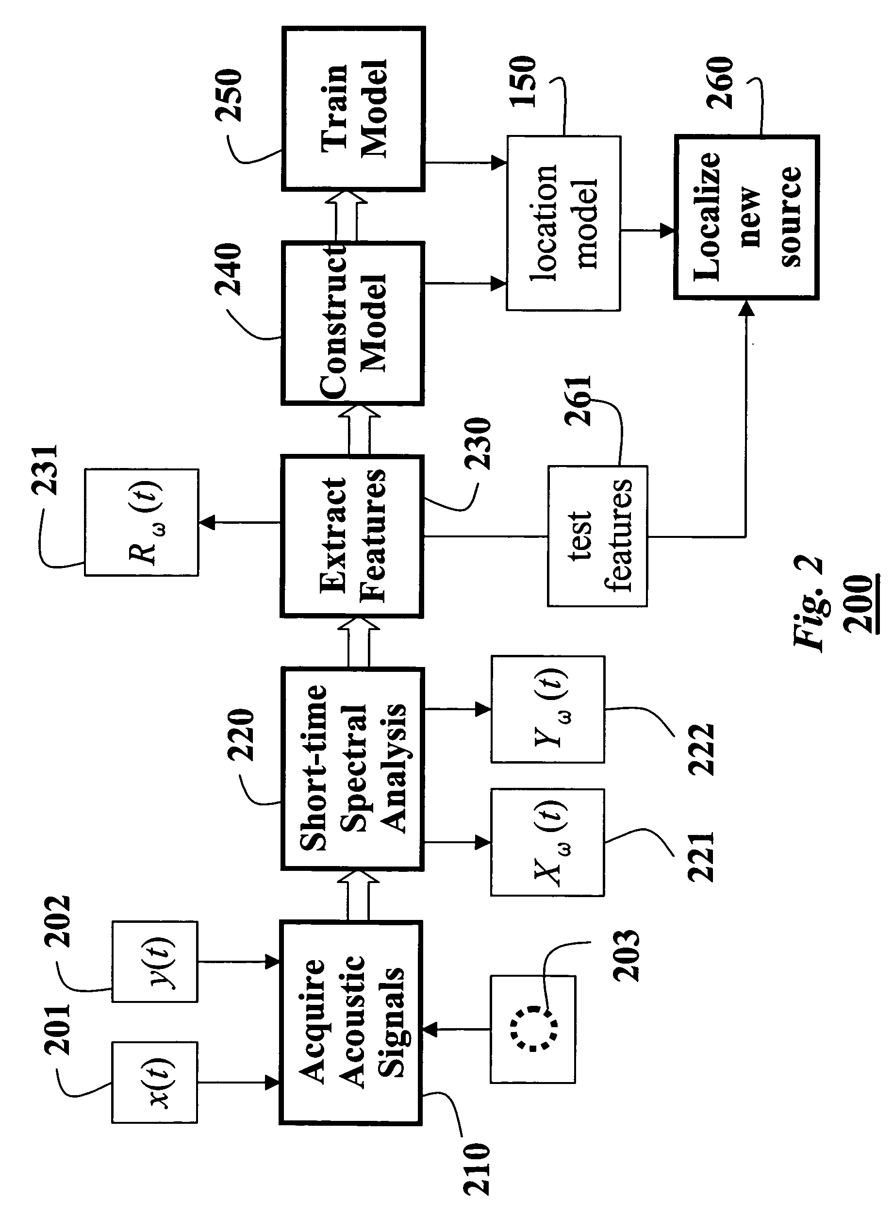
[0022]In order to have invariance from the nature of the acoustic source and microphone characteristics, we acquire relative acoustic features. We use the features to train a location model 150. Thus, the training is not influe...


PUM


Abstract

A method constructs a location model for locating and tracking sources of acoustic signals. Acoustic training signals are acquired from an acoustic training source at an unknown location in an environment with an array of microphones placed at unknown positions in the environment. From each acoustic training signal, relative acoustic features are extracted to construct a location model that is trained with the relative acoustic features.

Description

FIELD OF THE INVENTION[0001]This invention relates generally to acoustic signal processing, and more particularly to locating and tracking acoustic sources with an array of microphones.BACKGROUND OF THE INVENTION[0002]An array of microphones can be used to locate and track a source of acoustic signals, e.g., a speaker or vehicle. Generally, this is called source localization.[0003]One common method takes advantage of the time difference of arrival (TDOA) of the acoustic signal at the microphones. The TDOA can be estimated using a variety of techniques, “Special issue on time-delay estimation,” IEEE Transactions on Acoustics and Speech Signal Processing, vol. ASSP-29, June 1981, M. S. Brandstein, J. E. Adcock, and H. F. Silverman, “A practical time delay estimator for localizing speech sources with a microphone array,” Computer Speech and Language, vol. 9, pp. 153-169, April 1995, C. H. Knapp and G. C. Carter, “The generalized correlation method for estimation of time delay,” IEEE Tr...

Claims


Application Information

Patent Timeline
Patent Type & Authority Patents(United States)
IPC IPC(8): H04R1/02
CPCH04R3/12G01S5/18G01S5/0252H04R2499/13
Inventor SMARAGDIS, PARISBOUFOUNOS, PETROS
Owner MITSUBISHI ELECTRIC RES LAB INC
Learn More