Canine habitat

Inactive Publication Date: 2009-09-08
JACKSON THOMAS J
View PDF22 Cites 41 Cited by
  • Summary
  • Abstract
  • Description
  • Claims
  • Application Information

AI Technical Summary

Benefits of technology

[0008]Modules may also be joined and stacked vertically. Each section has a plurality of indentations on a surface which face inward toward a cavity of each section. When the sections are joined to form a module, the indentations of a lower section complement the indentations of an upper section, with the plurality of indentations of the lower and upper sections facing inward toward the module cavity. When a second module is placed on top of a first module, indentations on a lower surface of the second module oppose the indentations on an upper surface of the first module to form smaller cavities. The smaller cavities formed between the indentations may accept a beam or similar structural member or members, which add rigidity to the connection between the two modules. The beams may be fastened to both the lower surface of the second module and the upper surface of the first module at the indentations to secure modules together.
[0009]Within modules, additional accessories may be included

Problems solved by technology

Many domesticated animals experience varying degrees of separation anxiety when separated from their adopted pack; this anxiety sometimes results in destructiv

Method used


Image

  • Canine habitat
  • Canine habitat
  • Canine habitat

Examples


embodiment 100

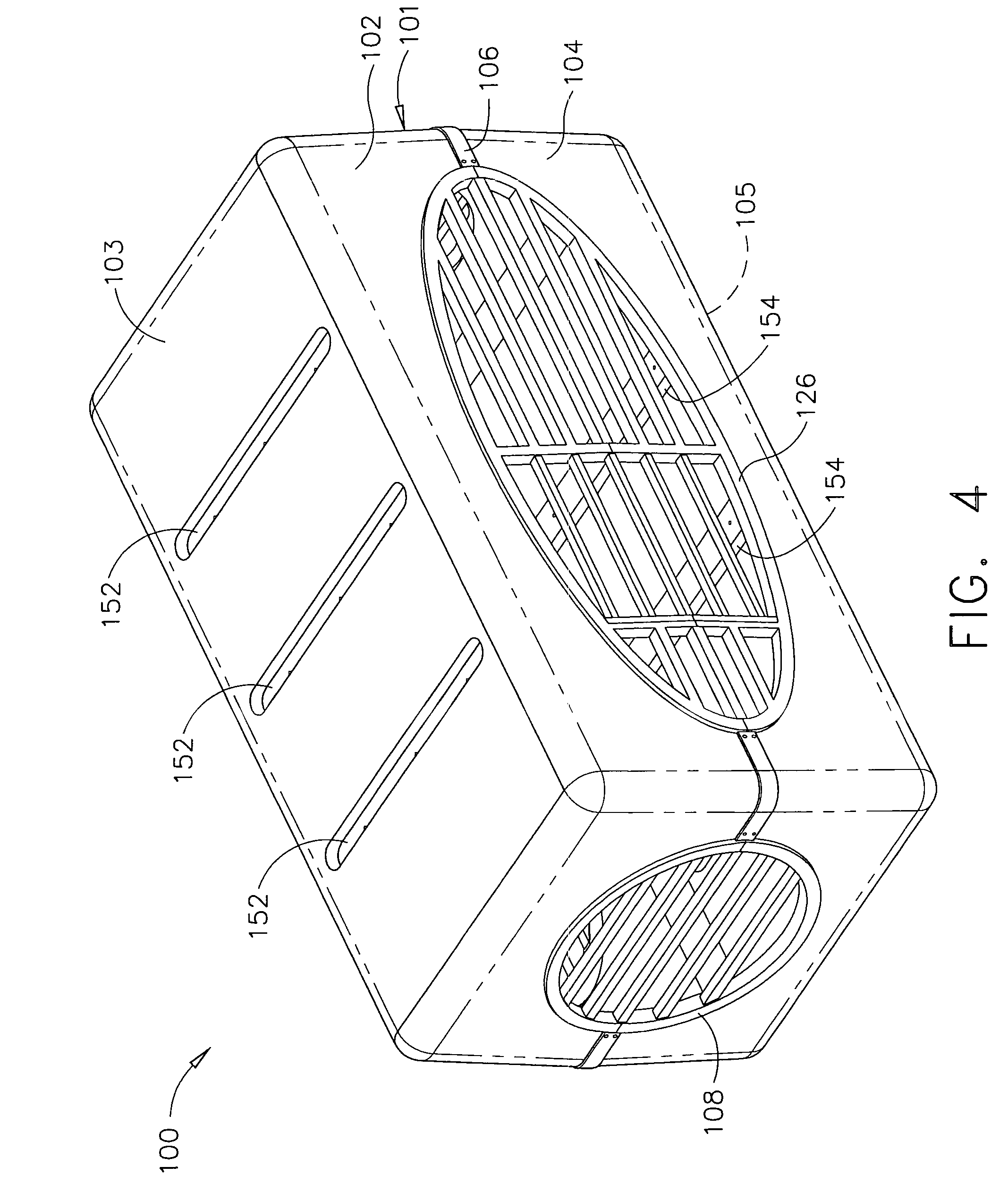
[0046]As shown in FIGS. 4-8, the embodiment 100 includes a habitat module 101. The upper module section 102 includes a plurality of indentations 152 on a planar face 103; the lower module section 104 includes a plurality of indentations 154 on a planar face 105. Indentations 152, 154 may include pre-drilled holes 156.

[0047]As shown in FIGS. 9-14, the module sections 107, 107a, 107b, 107c, 107d and 107e may be used as either upper or lower module sections in place of the upper module sections, 102, 104 to vary the openings in the habitat module 101. Shown in FIGS. 11-14, an opening 158 in surfaces 109b, 109c, 109d, and 109e is shown to be utilized if one module is used in a vertically stacked relationship with another module to allow for passage between two modules, as an opening 158 on any of modules sections 107b-e, used as a lower module section of an upper module, are aligned so as to complement an opening 158 on identical module sections 107b-3, used as a upper module section of...

second embodiment

[0053]a door grate 186 is shown in FIG. 26 which has engagement flanges 188, 190 and a plurality of horizontal tube members 192 and vertical door supports 194. Located on the vertical door supports 194 are a plurality of pins 198 which engage a removable section 200 at slots 202 in vertical ends 196. To provide an opening for an animal to enter into or exit the habitat 100, the removable section 200 is lifted upwardly and outwardly from a module to disengage the removable section 200 from the pins 198.

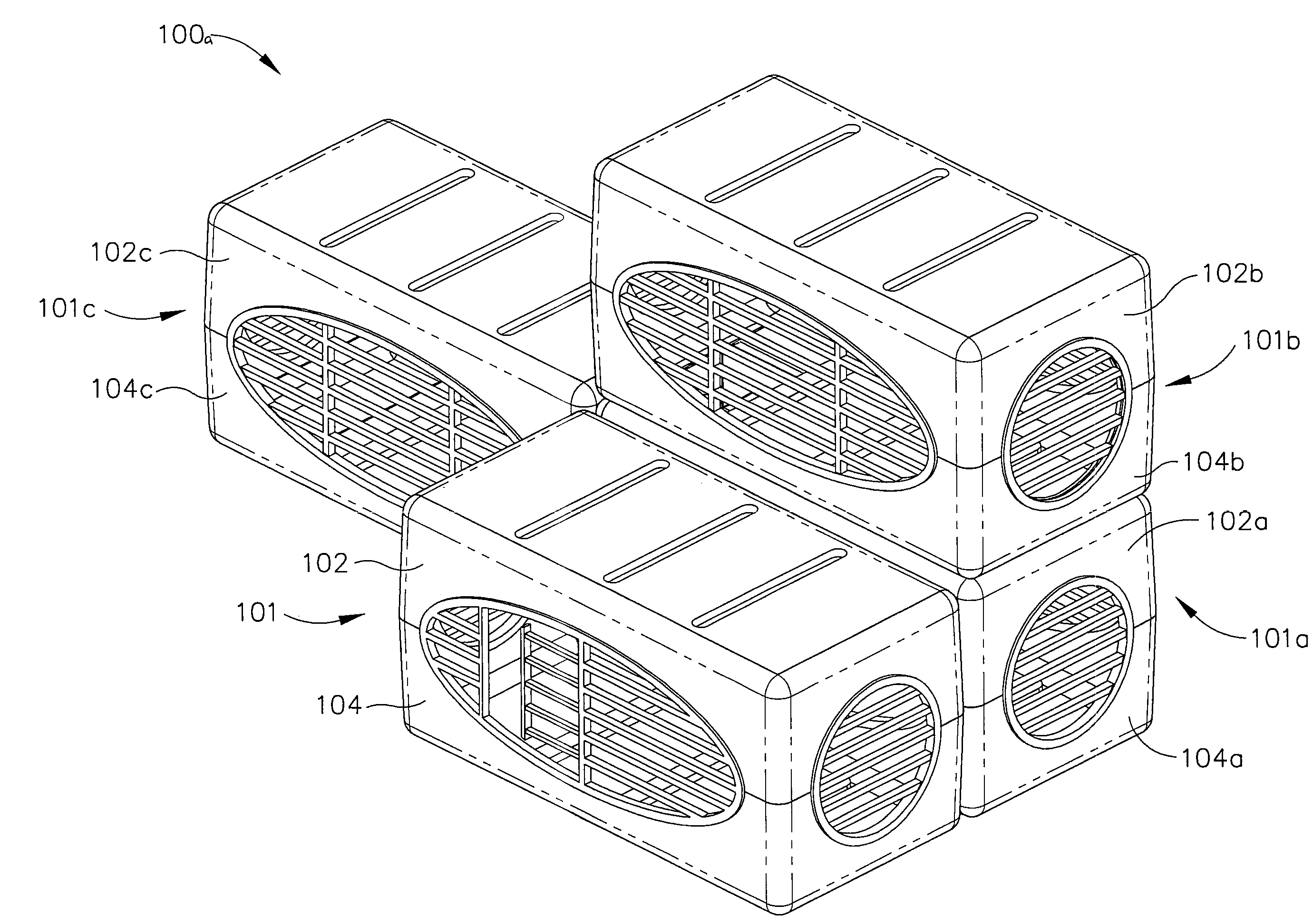
[0054]In operation, the embodiment 100, as shown in FIGS. 4-8, may have one module including a door grate 126 or 186 as the only opening to enter into and exit the module. Additional varieties of accessories such as additional openings and grates 108, 116, shelves 180, equipment 204 and trays 178 may be added to the one-module habitat 100. To expand the animal habitat 100, additional modules may be joined laterally and vertically to form an animal habitat such as the one shown in FIG. ...


PUM


Abstract

An animal habitat is disclosed for confining an animal in a livable area that may adapted to have distinct areas. The habitat may be formed of sections are used to form modules. The modules may be joined by attaching two or more modules laterally, or the modules may be joined by vertical stacking. Grates are placed in openings within outer walls of the modules. One type of grate allows attachment of monitoring and feeding equipment, while others are utilized as doors. Animals contained in a module can pass into laterally attached modules. A staircase and an opening in an upper section of a module allows animals to travel between a lower module to an upper module. Other accessories such as a tray and monitoring devices may be included as desired in one or more module.

Description

CROSS REFERENCE TO RELATED APPLICATIONS[0001]This application claims the benefit of U.S. provisional application Ser. No. 60 / 755,468, filed Dec. 30, 2005 the disclosure of which is hereby incorporated by reference.BACKGROUND OF THE INVENTION[0002]Modern domesticated animals have descended from wild animals and have inherited certain basic instincts, including feeling comfortable and protected in small confined areas during rest. A travel kennel or crate is a small confined area like a den, yet an animal can be trapped in a small kennel or crate with little opportunity to exercise or move around. Domesticated animals have also inherited an instinct not to soil the areas they use for food and water. Many domesticated animals are pack animals and consider their master and family an adopted pack. Many domesticated animals experience varying degrees of separation anxiety when separated from their adopted pack; this anxiety sometimes results in destructive behavior such as chewing and hou...

Claims


Application Information

Patent Timeline
IPC IPC(8): A01K1/03A01K1/02A01K31/06
CPCA01K1/034A01K1/033
Inventor JACKSON, THOMAS J.
Owner JACKSON THOMAS J
Why Eureka
Try Eureka