Clamp member for a marine propulsion device

Active Publication Date: 2009-09-08
BRUNSWICK CORPORATION
View PDF7 Cites 9 Cited by
  • Summary
  • Abstract
  • Description
  • Claims
  • Application Information

AI Technical Summary

Problems solved by technology

However, because of corrosion problems, aluminum clamping plates can present serious potential problems resulting from galvanic corrosion of the aluminum material.
The use of stainless steel clamping plate

Method used


Image

  • Clamp member for a marine propulsion device
  • Clamp member for a marine propulsion device
  • Clamp member for a marine propulsion device

Examples


Embodiment Construction

[0025]Throughout the description of the preferred embodiment of the present invention, like components will be identified by like reference numerals.

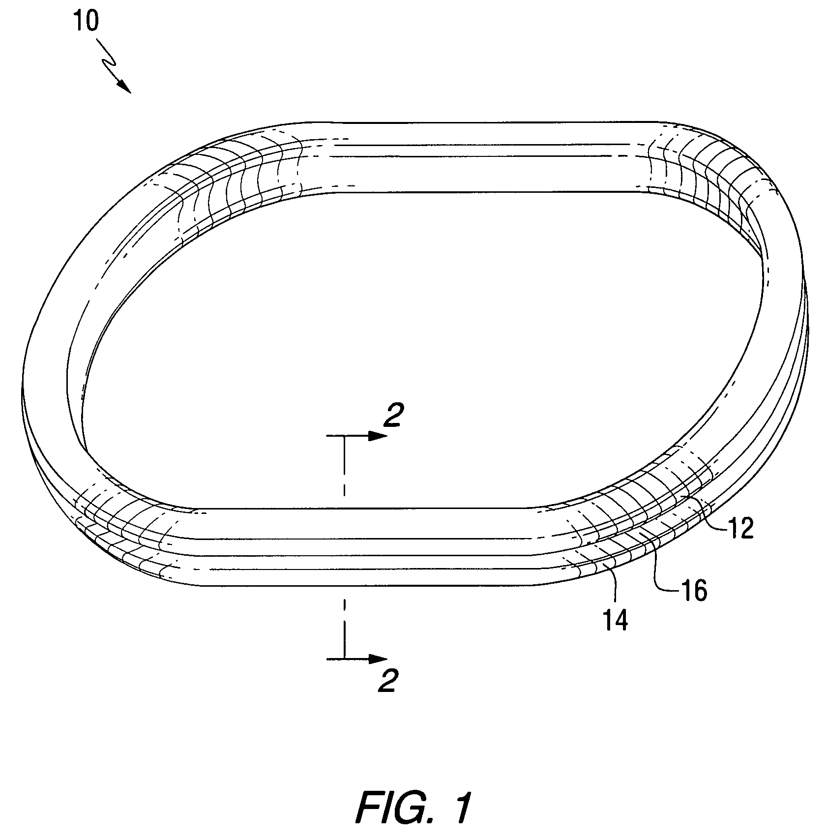
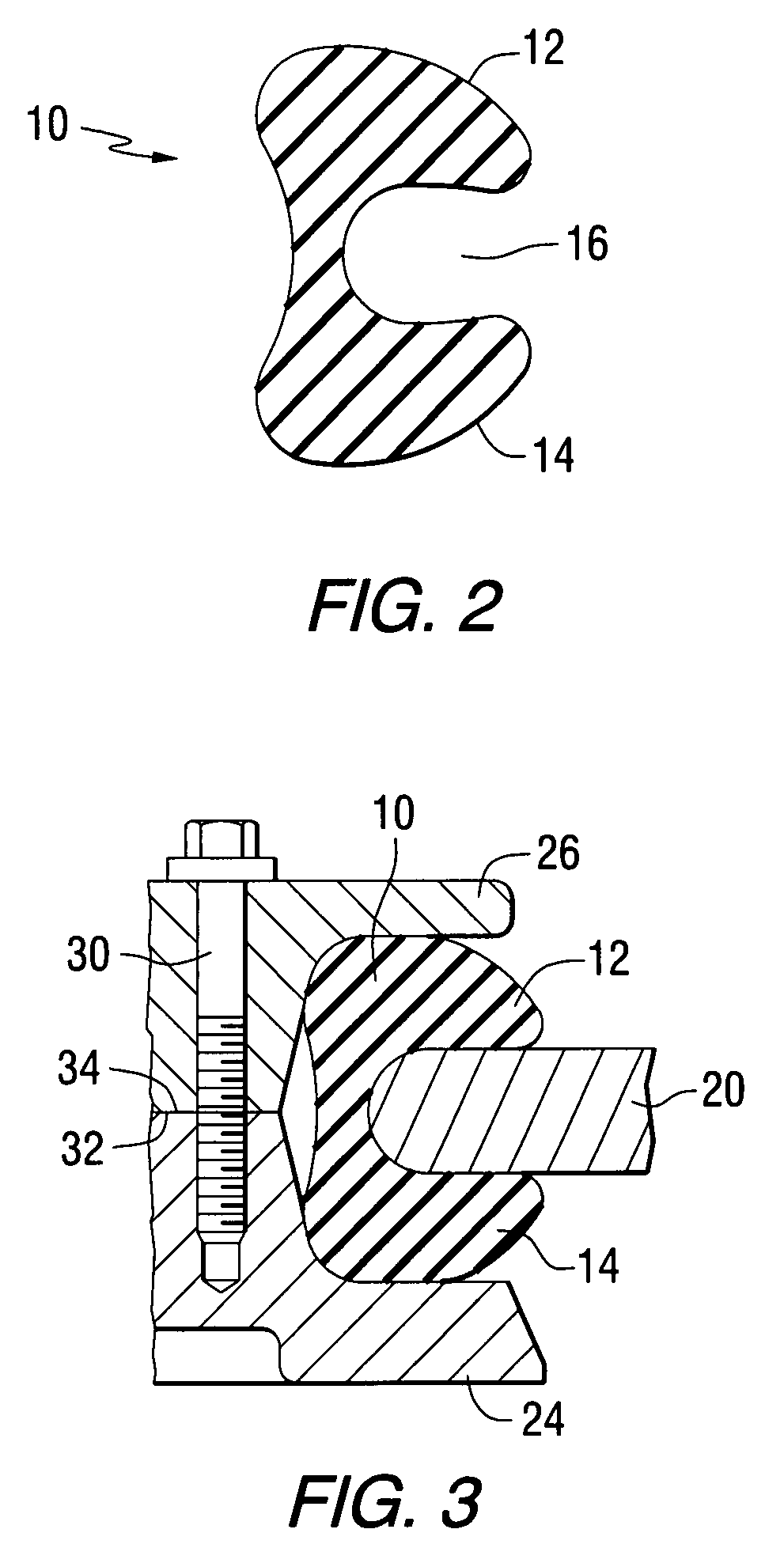
[0026]FIG. 1 is an isometric representation of an elastomeric seal 10, or grommet, that is generally similar to the one that is described in U.S. patent application Ser. No. 11 / 586,191 which is described above. FIG. 2 is a cross-sectional view of the seal 10. Although the present invention, which will be described in greater detail below, can be used with various shapes of seals, the seal shown in FIGS. 1 and 2 is particularly suited for use in conjunction with the clamp member of the present invention.

[0027]With continued reference to FIGS. 1 and 2, the seal 10 comprises an upper lobe 12, a lower lobe 14, and a space 16 between the upper and lower lobes.

[0028]FIG. 3 shows the seal 10 disposed around a portion 20 of a hull of a marine vessel. A lower clamping plate 24 and an upper plate 26 compress the seal 10 against outer surfaces of ...


PUM


Abstract

A clamp member is provided with numerous lightening holes which comprise cavities and depressions formed on an inner surface of the clamp member. Bolt holes are provided through upper and lower surfaces of the clamp member and extend through the cavities. A reduced volume of the clamp member allows it to be manufactured from materials that are generally heavier than aluminum, but less susceptible to galvanic corrosion.

Description

BACKGROUND OF THE INVENTION[0001]1. Field of the Invention[0002]The present invention is generally related to a clamp member for a marine propulsion device and, more particularly, to a clamp member that compresses an elastomeric seal component for a marine propulsion device that extends through the hull of a marine vessel.[0003]2. Description of the Related Art[0004]It is well known to those skilled in the art that marine propulsion devices can be configured to extend downwardly through the hull of a marine vessel. These marine propulsion systems are typically steerable about a generally vertical steering axis. Because of their position relative to the hull of the marine vessel, it is very important that effective seals, or grommets, are used to prevent leakage through the opening that is necessary to allow the marine propulsion device to extend downwardly below the marine vessel. In addition, those skilled in the art of marine propulsion systems are also aware of many other types o...

Claims


Application Information

Patent Timeline
IPC IPC(8): F16M1/00
CPCB63H20/02F16J15/106B63H21/30
Inventor EICHINGER, CHARLES H.
Owner BRUNSWICK CORPORATION
Why Eureka
Try Eureka