Vehicle surroundings monitoring apparatus

a technology for monitoring apparatus and vehicle surroundings, applied in scene recognition, television systems, instruments, etc., can solve problems such as cost increase, and achieve the effects of reducing apparatus cost, reducing relative speed, and shortening vehicle arrival tim

Active Publication Date: 2009-09-08
ARRIVER SOFTWARE AB
View PDF7 Cites 28 Cited by
  • Summary
  • Abstract
  • Description
  • Claims
  • Application Information

AI Technical Summary

Benefits of technology

[0009]According to the above invention, if the monitored object around the vehicle is imaged more than once at the predetermined time intervals, a change in size of the image portion of the monitored object at each time becomes more significant in the taken image as the relative speed between the monitored object and the vehicle increases. Moreover, the higher the relative speed is, the shorter the vehicle arrival time is. Therefore, the arrival time estimation process unit estimates the vehicle arrival time based on the rate of change in size of the image portion of the identical monitored object calculated by the rate-of-change calculation process unit, by which the surroundings of the vehicle can be monitored. According to the present invention, the vehicle arrival time can be estimated from the image taken by the single camera in this manner, thereby reducing cost of the apparatus in comparison with a case of using two cameras. In addition, this facilitates camera mounting on the vehicle.
[0031]According to the above invention, if the monitored object around the vehicle is imaged more than once at the predetermined time intervals, a change in size of the image portion of the monitored object at each time becomes more significant in the taken image as the relative speed between the monitored object and the vehicle increases. Moreover, the higher the relative speed is, the shorter the vehicle arrival time is. Therefore, the computer can calculate the rate of change in size of the image portion of the identical monitored object by performing the monitored object extraction step and the rate-of-change calculation step and can estimate the vehicle arrival time by performing the arrival time estimation step. Then, the surroundings of the vehicle can be monitored by the vehicle arrival time. Since the vehicle arrival time can be estimated from the image taken by the single camera in this case, it is possible to reduce cost of the apparatus in comparison with a case of using two cameras. In addition, this facilitates camera mounting on the vehicle.

Problems solved by technology

Where the distance between the vehicle and the monitored object is detected based on the parallax in this way, however, there has been a problem of an increase in cost caused by provision of two cameras and requiring a complicated work for installation such as strict adjustments of optical axes of these cameras.

Method used


Image

  • Vehicle surroundings monitoring apparatus
  • Vehicle surroundings monitoring apparatus
  • Vehicle surroundings monitoring apparatus

Examples


first embodiment

[0051]The following describes a method of estimating the time to arrival at the vehicle 10 of the object monitored by the image processing unit 1 according to the first embodiment of the present invention with reference to FIG. 3. In FIG. 3, Im1 designates an image taken by the infrared camera 2 at an imaging time point t11 and Im2 designates an image taken by the infrared camera 2 at a time point t10 which is a time interval dT (corresponding to the predetermined time interval according to the present invention) later than the time point t11.

[0052]Im1 includes an image portion 31 of a pedestrian as a monitored object and Im2 includes an image portion 30 of the identical pedestrian. Referring to FIG. 3, there is shown a situation in which the pedestrian is walking toward the vehicle 10. The width w10 of the image portion 30 of the pedestrian in Im2 is greater than the width w11 of the image portion 31 of the pedestrian in Im1 since the pedestrian comes closer to the vehicle at the i...

second embodiment

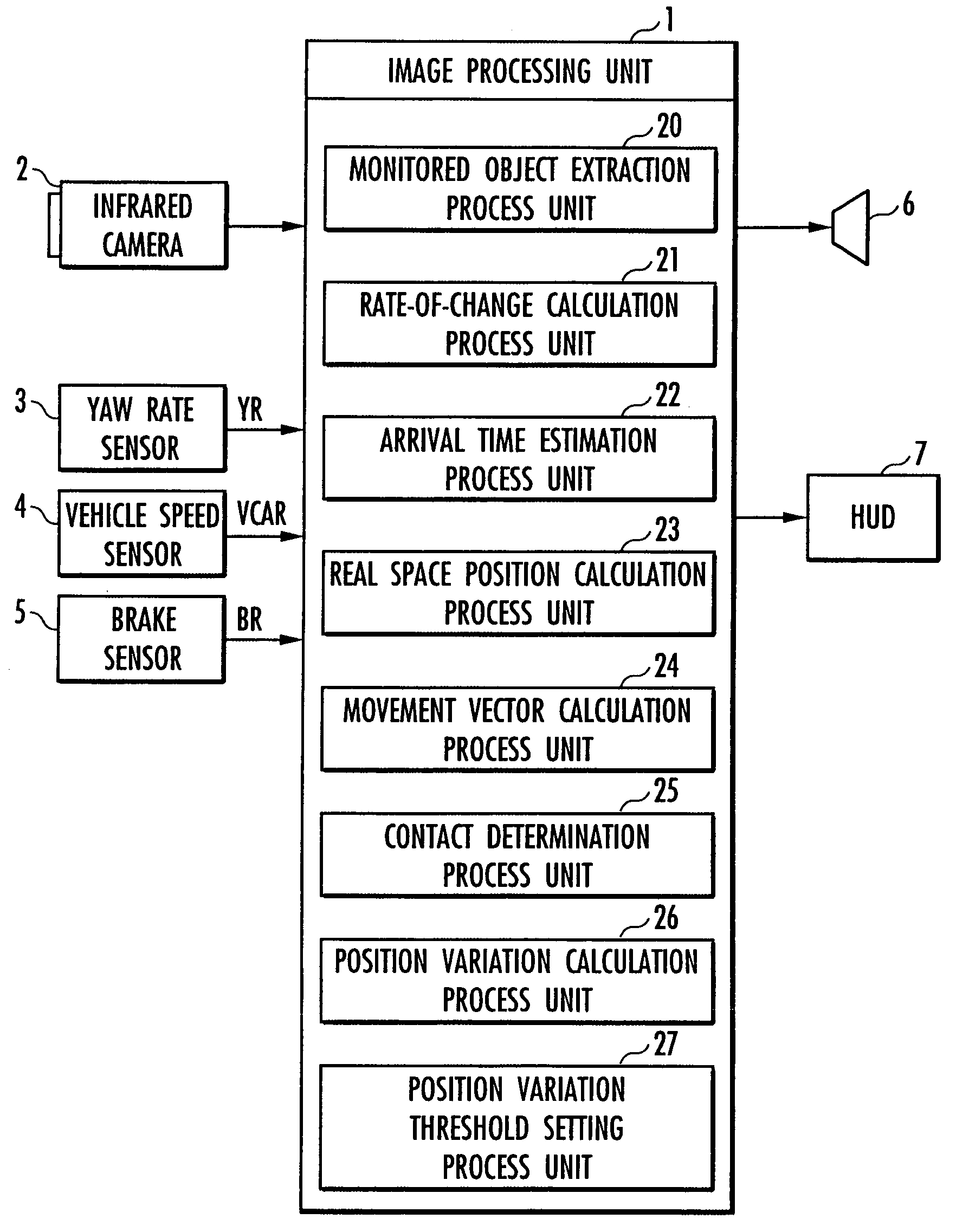
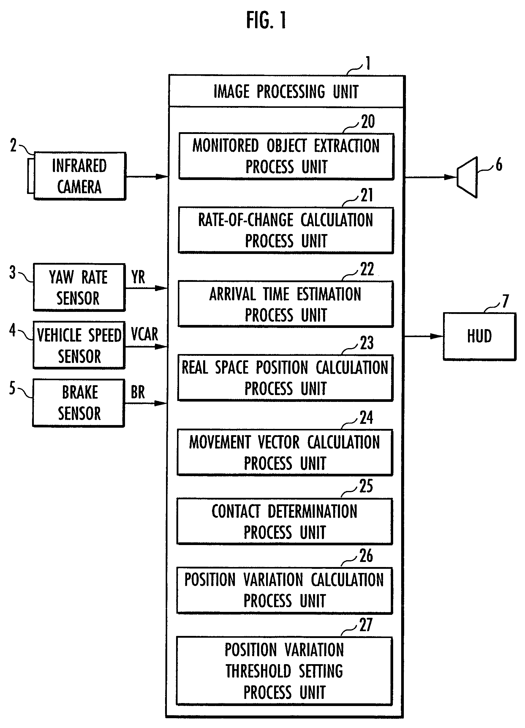
[0056]Subsequently, an execution procedure for a contact determination process between the monitored object and the vehicle 10 performed by the image processing unit 1 according to a second embodiment of the present invention will be described with reference to a flowchart shown in FIG. 4. The image processing unit 1 inputs an image signal, which is output from the infrared camera 2 in step 1, first, and then captures a grayscale image converted from the image signal to digital tone (luminance) data into the image memory in step 2. In the next step 3, the image processing unit 1 obtains a binary image by binarization in which a value of “1” (white) is set if the luminance value of a pixel is a predetermined threshold value or greater and a value of “0” (black) is set otherwise for each pixel of the grayscale image.

[0057]The subsequent steps 4 to 6 correspond to processes performed by the monitored object extraction process unit 20. The monitored object extraction process unit 20 cal...

third embodiment

[0093]The following describes an execution procedure for the contact determination process between the monitored object and the vehicle 10 performed by the image processing unit 1 according to a third embodiment of the present invention with reference to a flowchart shown in FIG. 8. Processing of step 30 to step 37 in FIG. 8 is similar to the above processing of step 1 to step 8 in FIG. 4. In step 37, the rate-of-change calculation process unit 21 calculates the rate of change Rate.

[0094]The next step 38 is performed by the position variation calculation process unit 26. The position variation calculation process unit 26 calculates the position variations Δx (horizontal direction) and Δy (vertical direction) of the image portion of the identical monitored object in the plurality of images used in the tracking at time intervals of step 37. Processing of the next step 39 to step 40 and step 50 is performed by the contact determination process unit 25. The contact determination process...


PUM


Abstract

A vehicle surroundings monitoring apparatus which determines whether there is a possibility of contact between a vehicle and a monitored object around the vehicle with a single camera mounted thereon. It includes a monitored object extraction process unit (20) which extracts an image portion of the monitored object from an image taken by a single infrared camera (2), a rate-of-change calculation process unit (21) which calculates a rate of change in size of the image portion of an identical monitored object extracted by the monitored object extraction process unit (20) from a plurality of images taken by the infrared camera (2) at predetermined time intervals, an arrival time estimation process unit (22) which estimates the time to arrival of the monitored object at the vehicle based on the rate of change, a real space position calculation process unit (23) which calculates a position of the monitored object in the real space based on the rate of change, a movement vector calculation process unit (24) which calculates a movement vector from a displacement of the position of the monitored object in the real space, and a contact determination process unit (25) which determines whether there is a possibility of contact between the monitored object and the vehicle.

Description

BACKGROUND OF THE INVENTION[0001]1. Field of the Invention[0002]The present invention relates to a vehicle surroundings monitoring apparatus which detects a monitored object existing around a vehicle from images obtained by a camera mounted on the vehicle and monitors the surroundings of the vehicle.[0003]2. Related Background Art[0004]Conventionally, there has been suggested a vehicle surroundings monitoring apparatus which has two cameras mounted on a vehicle and detects a distance between a monitored object and the vehicle by the principle of triangulation based on a difference (parallax) between image portions of the identical monitored object extracted from images of the surroundings of the vehicle taken by the cameras (for example, refer to Japanese Patent Laid-Open No. 2001-6096).[0005]According to the conventional vehicle surroundings monitoring apparatus, the distance between the monitored object around the vehicle and the vehicle is calculated. Then, the vehicle surroundin...

Claims


Application Information

Patent Timeline
Patent Type & Authority Patents(United States)
IPC IPC(8): B60Q1/00
CPCB60W50/14G06K9/00805G06K9/6289B60W2420/42G06V20/58G06V10/803G06F18/251
Inventor NAGAOKA, NOBUHARUTSUJI, TAKAYUKI
Owner ARRIVER SOFTWARE AB
Why Eureka
Try Eureka