Icemaker system for a refrigerator

a technology for refrigerators and icemakers, applied in the field of refrigerators, can solve problems such as the decreasing of the ice production tim

Inactive Publication Date: 2009-09-15
MAYTAG
View PDF12 Cites 48 Cited by
  • Summary
  • Abstract
  • Description
  • Claims
  • Application Information

AI Technical Summary

Problems solved by technology

The flow of air disturbs a thermal barrier that is present at the ice mold increasing temperature transfer rates and, as a consequence, decreasing ice production time.

Method used


Image

  • Icemaker system for a refrigerator
  • Icemaker system for a refrigerator
  • Icemaker system for a refrigerator

Examples


Embodiment Construction

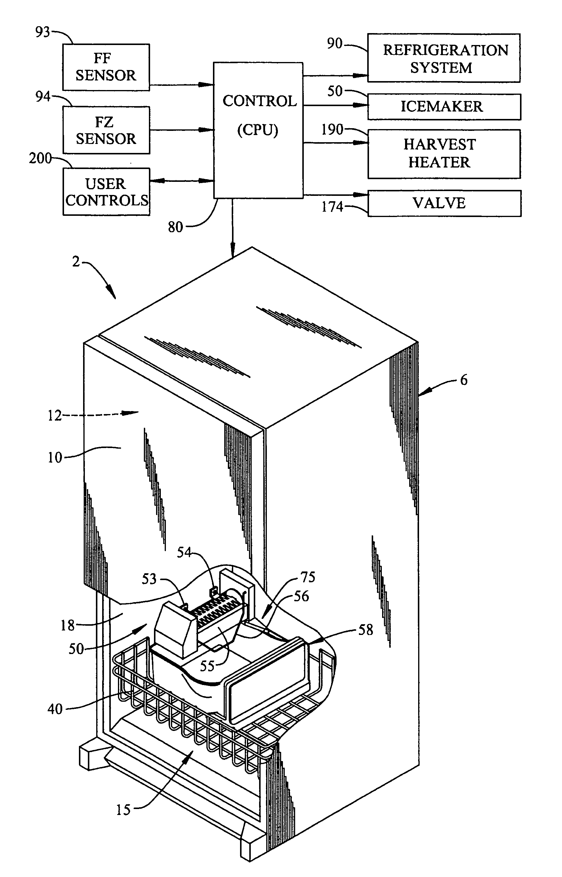
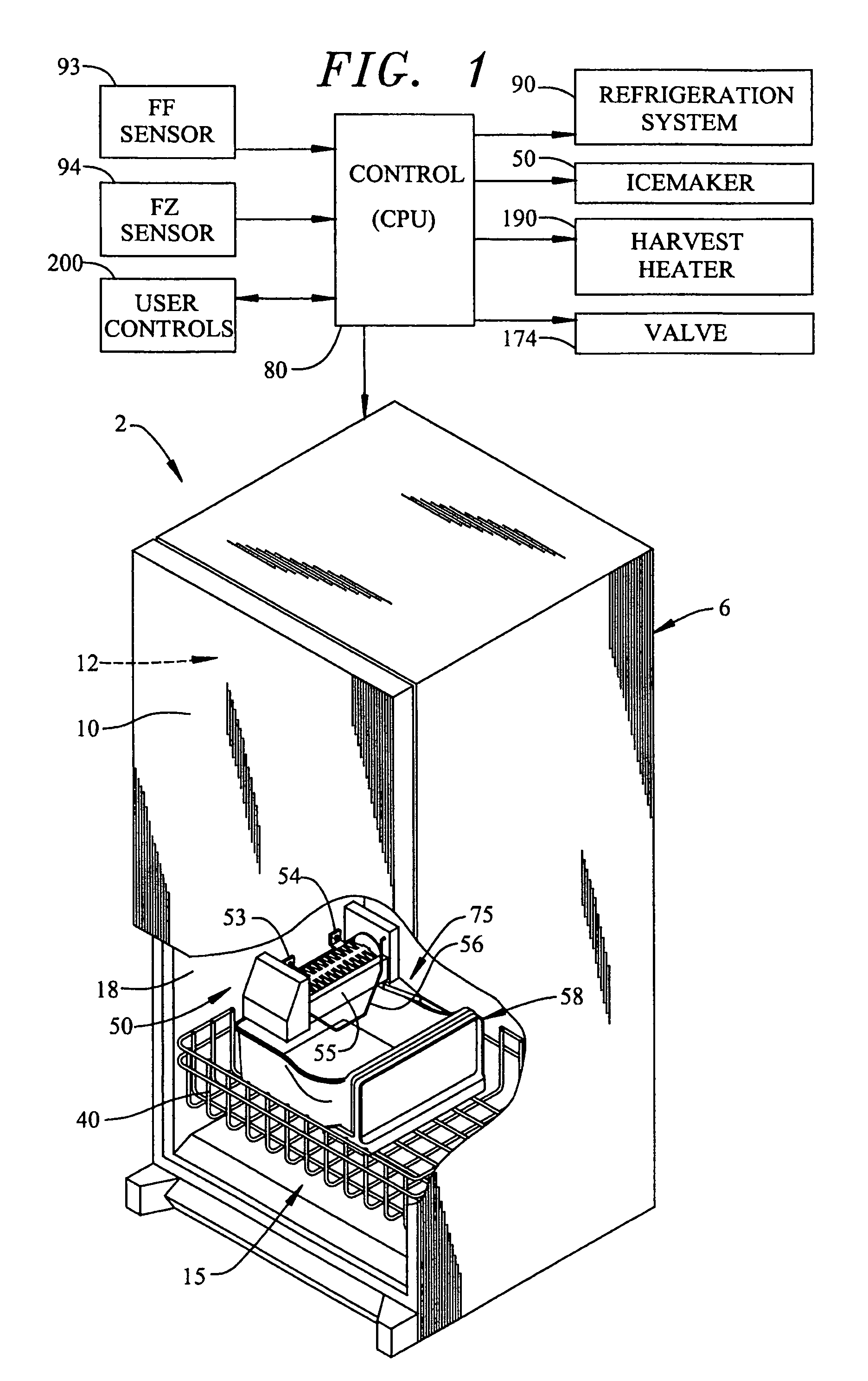
[0013]With initial reference to FIGS. 1 and 2, a refrigerator constructed in accordance with the present invention is generally indicated at 2. As shown, refrigerator 2 includes a cabinet shell 6 provided with an upper fresh food compartment door 10 which is adapted to close off an upper fresh food compartment 12. As known in the art, fresh food door 10 is adapted to pivot about a vertical axis defined by upper and lower hinges (not shown). Within cabinet shell 6 is also defined a freezer compartment, generally indicated at 15, which is defined by a liner 18. Although not shown, freezer compartment 15 is adapted to be closed off by means of a door. With this general construction, refrigerator 2 defines a bottom mount style unit. As known in the art, the door associated with freezer compartment 15 can either be mounted for a pivotable movement about a vertical axis similar to fresh food door 10, or mounted upon slide assemblies which permit linear shifting of the freezer door relativ...


PUM


Abstract

An icemaker system provided in a refrigerator is designed to reduce an amount of time required to produce ice. The refrigerator includes a refrigeration system including a number of refrigeration components and a refrigeration loop. The refrigeration loop includes an icemaker section that carries a flow of refrigerant to an ice mold portion of the icemaker system and a bypass section that isolates the icemaker system from the flow of refrigerant. A control system automatically activates the icemaker system regardless of a need for cooling. That is, upon sensing a demand for ice, the control system opens a valve to cause refrigerant to flow through the icemaker section and activates the refrigeration components to speed ice production whether or not additional cooling is required in fresh food and / or freezer compartments.

Description

BACKGROUND OF THE INVENTION[0001]1. Field of the Invention[0002]The present invention pertains to the art of refrigerators and, more particularly, to an icemaker system for in a refrigerator.[0003]2. Discussion of the Prior Art[0004]Whether it be to ensure an adequate amount of ice for a party or keep up with daily demand, there is always a need to decrease ice production time. In the art of refrigerated appliances, it is known to employ fans or other similar devices to decrease an amount of time required to produce ice. Typically, the fan is oriented to direct air from an evaporator portion of the refrigerator across an ice mold. The flow of air disturbs a thermal barrier that is present at the ice mold increasing temperature transfer rates and, as a consequence, decreasing ice production time.[0005]While the above arrangements utilize fans to blow evaporator air across the ice mold, other arrangements directly expose the ice mold to the evaporator. The evaporator is part of a prim...

Claims


Application Information

Patent Timeline
Patent Type & Authority Patents(United States)
IPC IPC(8): F25C1/00F25B49/00
CPCF25C5/187F25D21/08F25B5/04F25B2400/0409F25B2600/0253F25B2600/11Y02B30/741F25D2400/30F25D2700/12F25D2700/122F25C2600/04Y02B30/70
Inventor KOPF, BRUCE A.
Owner MAYTAG
Why Eureka
Try Eureka