Small ultra wideband antenna having unidirectional radiation pattern

a technology of unidirectional radiation and ultra wideband antennas, applied in the direction of slot antennas, antennas, electrically short antennas, etc., can solve the problems of unidirectional radiation pattern of portable communication appliances, antenna size, and difficulty in miniaturizing communication appliances, so as to improve the characteristic impedance

Active Publication Date: 2009-09-15
SAMSUNG ELECTRONICS CO LTD
View PDF9 Cites 233 Cited by
  • Summary
  • Abstract
  • Description
  • Claims
  • Application Information

AI Technical Summary

Benefits of technology

[0016]The UWB antenna may further comprise a delay part, provided to connect the power feeding part with the dipole radiator on the upper surface of the substrate, for delaying a time point where the electromagnetic energy is supplied to the dipole radiator.
[0029]The loop radiator may include an active loop radiator having one end connected to the signal terminal and the other end connected to the first ground terminal, excited by the electromagnetic energy fed through the signal terminal, enhancing the electromagnetic waves radiating in one direction from the dipole radiator, and canceling the electromagnetic fields produced in the other direction from the dipole radiator; and at least one passive loop radiator excited by an induced electromagnetic energy induced by the dipole radiator and the active loop radiator, enhancing the electromagnetic waves radiating in one direction from the dipole radiator, and canceling the electromagnetic fields produced in the other direction from the dipole radiator.
[0038]The width of the second slot line may be wider than the width of the first slot line to improve the characteristic impedance.

Problems solved by technology

Since communication is possible in the case where the radiation pattern is formed in the direction of a base station, a portable communication appliance requires a unidirectional radiation pattern.
Consequently, in order to perform a low frequency band communication, the size of the antenna should be increased, and this causes a difficulty in miniaturization of the communication appliance.
This substrate type dipole antenna has the advantage in that it can transmit a UWB signal and can be fabricated with a relatively small size, but has the problem that it cannot have a unidirectional radiation pattern.
Although this microstrip patch antenna has unidirectional radiation pattern and can be subminiaturized, it has the problem that it has a narrow bandwidth.

Method used


Image

  • Small ultra wideband antenna having unidirectional radiation pattern
  • Small ultra wideband antenna having unidirectional radiation pattern
  • Small ultra wideband antenna having unidirectional radiation pattern

Examples


Embodiment Construction

[0053]Certain exemplary embodiments of the present invention will be described in greater detail with reference to the accompanying drawings.

[0054]In the following description, same drawing reference numerals are used for the same elements even in different drawings. The matters defined in the description such as a detailed construction and elements are nothing but the ones provided to assist in a comprehensive understanding of the invention. Thus, it is apparent that the present invention can be carried out without those defined matters. Also, well-known functions or constructions are not described in detail since they would obscure the invention in unnecessary detail.

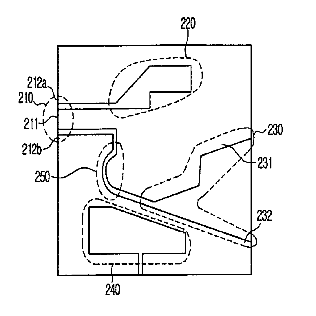
[0055]FIG. 3 is a view illustrating the structure of a UWB antennal according to an exemplary embodiment of the present invention.

[0056]Referring to FIG. 3, the UWB antenna according to an exemplary embodiment of the present invention includes a power feeding part 110, an active loop radiator 120, and a dipole radiato...


PUM


Abstract

A small ultra wideband (UWB) antenna designed to have a unidirectional radiation pattern is disclosed. The UWB antenna includes a substrate; a power feeding part, provided on an upper surface of the substrate, for receiving a supply of an external electromagnetic energy; a dipole radiator excited by the electromagnetic energy fed through the power feeding part and radiating electromagnetic waves in one and the other directions of the substrate; and an active loop radiator excited by the electromagnetic energy fed through the power feeding part, respectively enhancing and canceling the electromagnetic fields produced in one or the other directions of the substrate by the dipole radiator.

Description

[0001]This application claims priority, under 35 U.S.C. § 119(a), from Korean Patent Application Nos. 10-2005-0005078 filed Jan. 19, 2005 and 10-2005-0101159 filed on Oct. 26, 2005 in the Korean Intellectual Property Office, the entire contents of which are incorporated herein by reference.BACKGROUND OF THE INVENTION[0002]1. Field of the Invention[0003]Apparatuses consistent with the present invention relate to a small ultra wideband (UWB) antenna, and more particularly to a small UWB antenna designed to have a unidirectional radiation pattern by combining a loop radiator and a dipole radiator.[0004]2. Description of the Related Art[0005]All antennas are used to convert an electric signal into a specified electromagnetic wave to radiate the converted electromagnetic wave to free space, or to convert a received electromagnetic wave into an electric signal. UWB technology means a wireless transmission technology that directly transmits and receives an impulse signal without using an R...

Claims


Application Information

Patent Timeline
Patent Type & Authority Patents(United States)
IPC IPC(8): H01Q21/00
CPCH01Q13/085H01Q9/285
Inventor BALZOVSKY, EVGENY V.BUYANOV, YURI I.KIM, YONG-JINKOSHELEV, VLADIMIR I.KWON, DO-HOONLEE, SEONG-SOO
Owner SAMSUNG ELECTRONICS CO LTD
Why Eureka
Try Eureka