
Light source module and display device having the same

a technology of light source module and display device, which is applied in the field of light source, can solve the problems of large brightness deviation of light provided, unprovided uniform light to the liquid crystal panel, and useless dark space in the light guide plate, and achieve the effect of reducing the brightness deviation of ligh

Inactive Publication Date: 2009-09-22
LG DISPLAY CO LTD
View PDF1 Cites 8 Cited by
  • Summary
  • Abstract
  • Description
  • Claims
  • Application Information

AI Technical Summary

Benefits of technology

The solution achieves uniform light distribution across the light guide plate, enhancing the compactness of display devices and preventing damage from external impacts by ensuring the LEDs are securely positioned without additional fixing members.

Problems solved by technology

The LED, however, has large brightness deviations of light provided to a light incident surface of the light guide plate.
Consequently, uniform light is not provided to the liquid crystal panel.
In addition, since light is not provided to the liquid crystal panel at the dark spot regions of the light guide plate, useless dark space is formed in the light guide plate.
As a result, there is a limitation to compacting a light source module for use in small displays.
When an external impact occurs to the light guide plate, the light source may be damaged by a collision between the light guide plate and the light source.
However, since the securing members block light emitted from the light source toward the light guide plate, dark spaces are formed corresponding to the securing members so that portions of the light guide plates are darkened.

Method used


Image

  • Light source module and display device having the same
  • Light source module and display device having the same
  • Light source module and display device having the same

Examples


first embodiment

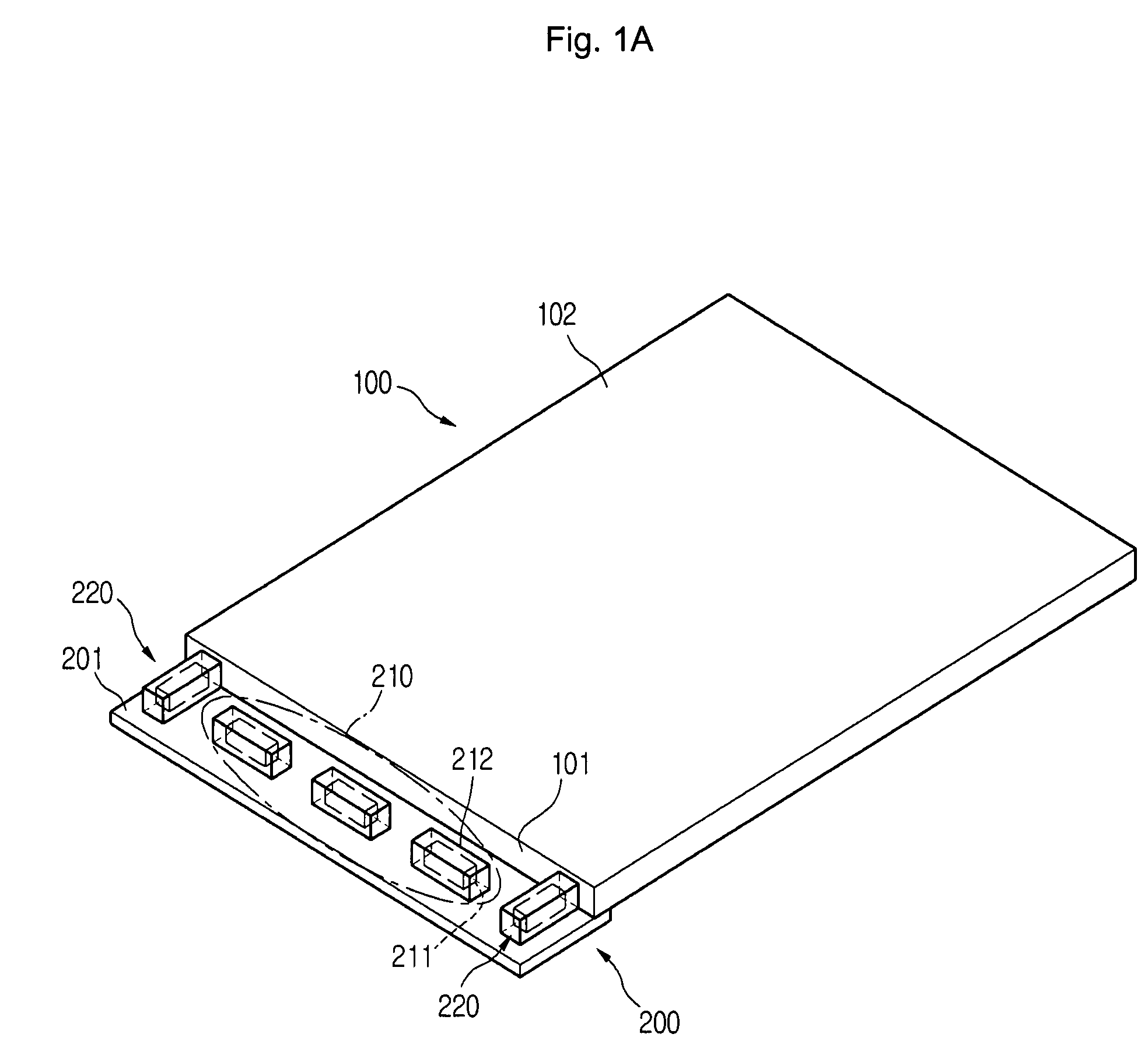
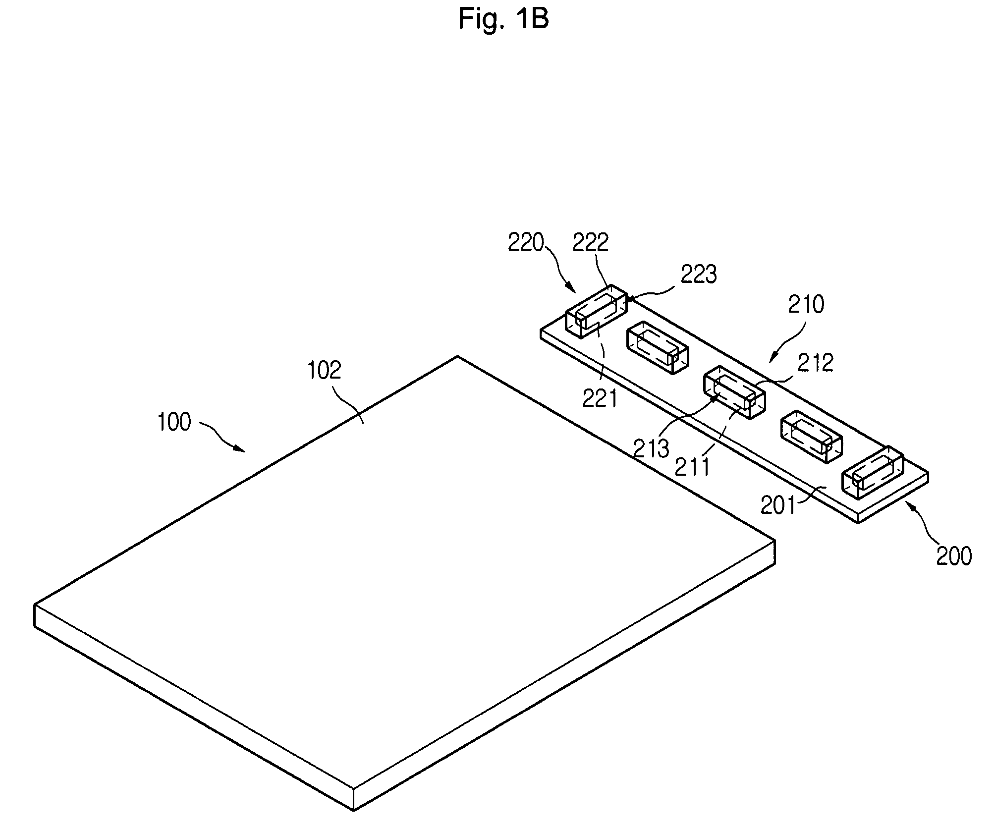
[0039]In this embodiment, the second light P2 emitted from the second light source 220 is reflected from the first light source 210 or the light source mounting surface 201 and then is provided to the dark spots of the light guide plate 100. In this way, the second light P2 is provided to a portion of the light guide plate 100 where the first light P1 is not provided, thereby reducing the brightness deviation of the light guide plate 100. In addition, since the second light source 220 secures and supports the light guide plate 100, a collision between the light guide plate 100 and the first light source 210 can be prevented. Therefore, the light source module according to the present invention requires no additional securing members.

[0040]FIGS. 2A to 2C illustrate a light source module according to a second embodiment of the present invention. Specifically, FIG. 2A is a perspective view of the light source module according to the second embodiment of the present invention, FIG. 2B i...

third embodiment

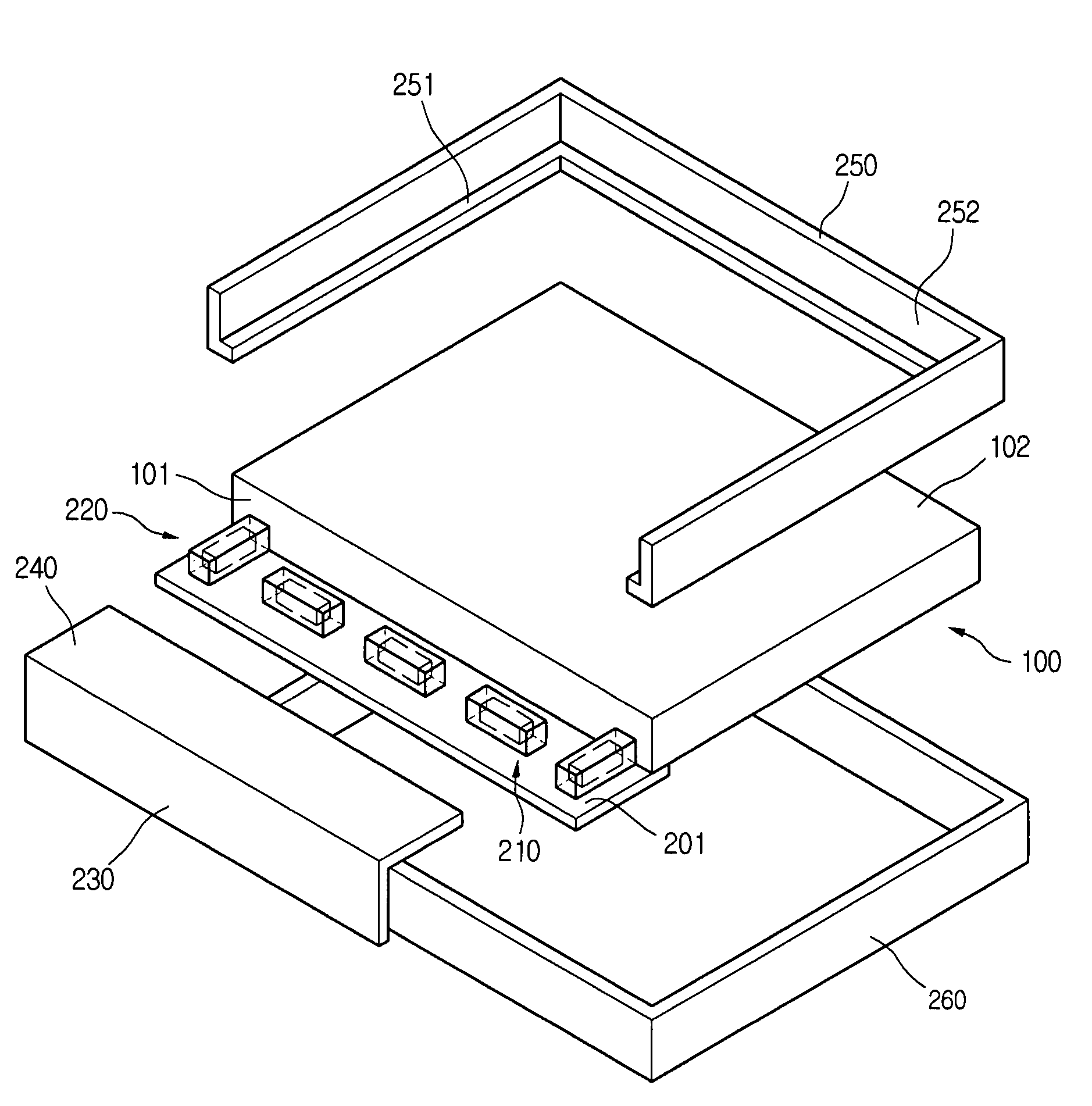
[0045]FIG. 3 is a perspective view of a light source module according to the present invention. The light source module shown in FIG. 3 has a structure substantially identical to that shown in FIGS. 2A to 2C, except for the use of a second light reflector 240 in addition to the first reflector 230. Duplicate description about the same components will be omitted for the purposes of conciseness and the same reference numbers and terms will be used to refer to the same components.

[0046]Referring to FIG. 3, the light source module includes a light guide plate 100, a board 200, a plurality of first light sources 210, a plurality of second light sources 220, a first light reflector 230, and a second light reflector 240 for reflecting light to the light guide plate. The second light reflector 240 faces a light source mounting surface 201 and is disposed on an edge of the first light reflector 230. The first light reflector 230 and the second light reflector 240 enclose the first and second...


PUM


Abstract

A light source module includes a light guide plate having a light incident surface receiving light and a light emitting surface emitting the received light, a board arranged adjacent to the light guide plate and having a light source mounting surface, at least one first light source disposed on the light source mounting surface of the board to provide a first light to the light incident surface of the light guide plate, and at least one second light source disposed on both sides of the light source mounting surface adjacent to the first light source to provide a second light toward the first light source.

Description

[0001]This invention claims the benefit of Korean Patent Application No. 10-2006-107561 filed in Korea on Nov. 2, 2006, which is hereby incorporated by reference in its entirety.BACKGROUND OF THE INVENTION[0002]1. Field of the Invention[0003]Embodiments of the present invention relate to a light source, and more particularly, to a light source module and a display device having the same.[0004]2. Description of the Related Art[0005]In recent years, research and development have been conducted on information processing devices that can process a large amount of data in a short amount of time as well as for the display devices that can display the processed data. More specifically, the display devices convert an electrical signal processed by the information processing devices into an image signal. Examples of such display devices include a liquid crystal display (LCD) device using liquid crystal, an organic light emitting device (OLED) using organic light emitting material, and a plas...

Claims


Application Information

Patent Timeline
Patent Type & Authority Patents(United States)
IPC IPC(8): F21V7/04
CPCG02B6/0088G02B6/0068G02B6/0055G02F1/1335
Inventor YEOM, MOON SOO
Owner LG DISPLAY CO LTD
Learn More