Socket connector with improved base

a socket connector and base technology, applied in the field of socket connectors, can solve the problem of easy destruction of the base housing, and achieve the effect of improving the housing

Inactive Publication Date: 2009-09-22
HON HAI PRECISION IND CO LTD
View PDF2 Cites 4 Cited by
  • Summary
  • Abstract
  • Description
  • Claims
  • Application Information

AI Technical Summary

Benefits of technology

[0007]Accordingly, an object of the present invention is to provide an electrical connector with improved housing.

Problems solved by technology

The joints also will cause the base housing be destroyed easily.

Method used


Image

  • Socket connector with improved base
  • Socket connector with improved base
  • Socket connector with improved base

Examples


Embodiment Construction

[0016]Reference will now be made to the drawing figures to describe a preferred embodiment of the present invention in detail.

[0017]Referring to FIG. 4, the electrical connector 1 includes a base 10, a cover 12 movably mounted on the base 10 and a lever 13 retained between the base 10 and the cover 12. The plate-like base 10 defines a retaining portion 100 at one end portion and a conduction area 109. The cover 12 defines a cover portion 120 corresponding to the retaining portion 100 and a plurality of openings 121 corresponding to the receiving grooves 101. The cover 12 further defines a plurality of protrusions 122 on the surface thereof for attaching an IC package to prevent the package from distortion. One end of the lever 13 is retained between the retaining portion 100 and the cover portion 120. Driving the other end of the lever 13 and then the cover 12 may move along the base 10.

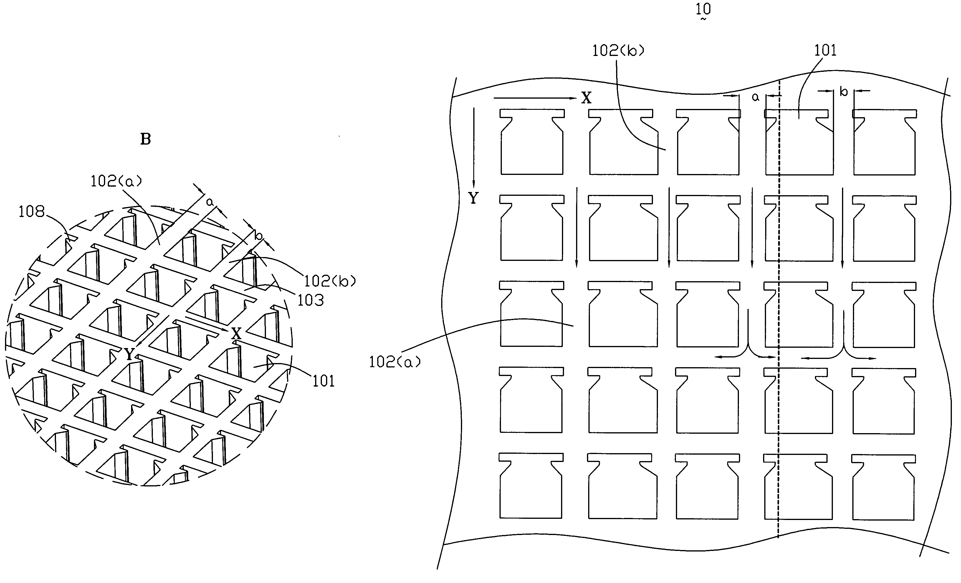
[0018]As FIGS. 5 and 6 shown, the conduction area 109 defines a receiving groove matrix having a ...


PUM


Abstract

An electrical connector (1) for electrically connecting an integrated circuit to a circuit board includes base (10) defining a plurality of receiving grooves (101) arranged in a matrix. The receiving grooves are arranged in rows and columns, one lengthways grid (102a / 102b) is defined between every two adjacent columns and one transverse grid (103) is defined between every two adjacent rows. The lengthways grids between different columns have different width.

Description

BACKGROUND OF THE INVENTION[0001]1. Field of the Invention[0002]The present invention relates to an electrical connector, and especially to a socket connector for connection of an IC package and a circuit member.[0003]2. Description of the Related Art[0004]Referring to FIG. 1 and FIG. 2, a conventional electrical connector 3 generally includes a base housing 31, a cover 32 movably mounted on the base housing 31 and a lever 33 movably driving the cover 32 to move along the base housing 31. The lever 13 is retained between the base 31 and the cover 32. An IC package disposed on the top of the cover 32 may connect or disconnect with a circuit board timely while the lever 33 rotates to drive the cover 32′ to move along the base housing 31. The conduction area 312 defines a plurality of receiving grooves 313 arranged in a matrix. Each receiving grooves 313 is of a square shape. Between every two adjacent receiving grooves there defines a transverse grid 314 in the X direction and a lengt...

Claims


Application Information

Patent Timeline
Patent Type & Authority Patents(United States)
IPC IPC(8): H01R13/625
CPCH05K7/1084
Inventor LU, MAO
Owner HON HAI PRECISION IND CO LTD
Why Eureka
Try Eureka