Automatic portable pneumatic compression system

a portable, pneumatic technology, applied in the field of medical devices, can solve the problems of difficult maneuverability and placement in the vicinity of patients, severe hampered clinical outcomes in real life, and inability to receive continuous treatment with a conventional devi

Inactive Publication Date: 2009-09-22
ZIMMER SURGICAL
View PDF17 Cites 70 Cited by
  • Summary
  • Abstract
  • Description
  • Claims
  • Application Information

AI Technical Summary

Problems solved by technology

Although showing high clinical efficacy in clinical studies in treating the above clinical indications, the conventional compression devices share many disadvantages that severely hamper their clinical out come in real life situations
Confinement to the bed for receiving continuous treatment with a conventional device is impractical and is hardly ever achieved.
The pump unit of the conventional compression device is heavy (5-15 pounds), which makes it hard to maneuver and place in the vicinity of the patients.
The pump unit is also big and thus creates a storage problem, specifically in hospitals, in which tens and hundreds of units are stationed, usually in a special storage room.
The sleeve of the conventional compression device is big and ungainly, and thus restricts the movement of the limb it encompasses and imposes discomfort.
In addition, the use of multiple cells demands the use of multiple conduits (usually one for each cell) making the whole system more cumbersome and harder to maneuver.
Furthermore, since the error detecting mechanism of the conventional systems shuts OFF the system each time an error is detected, the system needs to be manually restarted by the clinical staff, thereby requiring the clinical staff to manually re-enter the data corresponding to the pressure and compression cycles.
In other words, in view of the need to manually enter the data corresponding to the pressure and compression cycles upon each start-up of the compression system and in view of the shutting down of the system upon error detection, with the accompanying re-entry of data, the conventional compression systems are overly dependent upon clinical staff for operation, thereby unduly imposing on the workload of the clinical staff.
All of the aforementioned disadvantages result in poor patient and therapist (mainly nurses) compliance and compliant.
As a consequence, the conventional compression devices need large compressors that require high current supply, which forces the connection to the electrical outlets for power supply.
Thus, adding an accumulator to the console of a system that is otherwise miniature, mobile and battery operated makes the console, and hence the entire system, immobile, which destroys the advantages and benefits of a mobile system.

Method used


Image

  • Automatic portable pneumatic compression system
  • Automatic portable pneumatic compression system
  • Automatic portable pneumatic compression system

Examples


Embodiment Construction

[0085]The present invention will be described in connection with preferred embodiments; however, it will be understood that there is no intent to limit the present invention to the embodiments described herein. On the contrary, the intent is to cover all alternatives, modifications, and equivalents as may be included within the spirit and scope of the present invention as defined by the appended claims.

[0086]For a general understanding of the present invention, reference is made to the drawings. In the drawings, like reference have been used throughout to designate identical or equivalent elements. It is also noted that the various drawings illustrating the present invention are not drawn to scale and that certain regions have been purposely drawn disproportionately so that the features and concepts of the present invention could be properly illustrated.

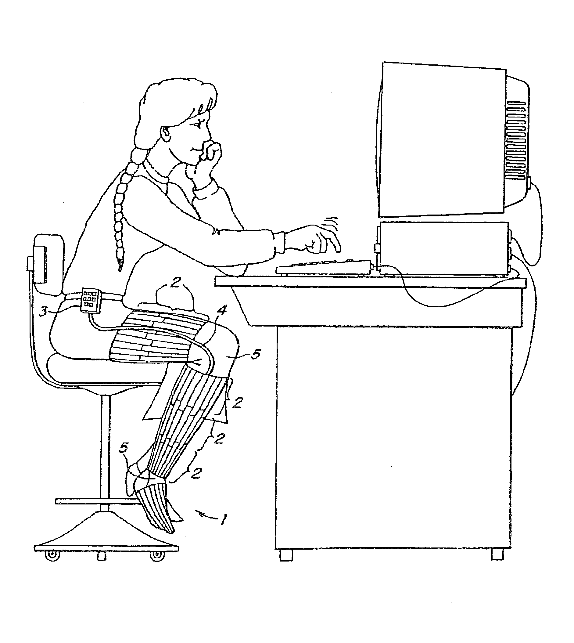
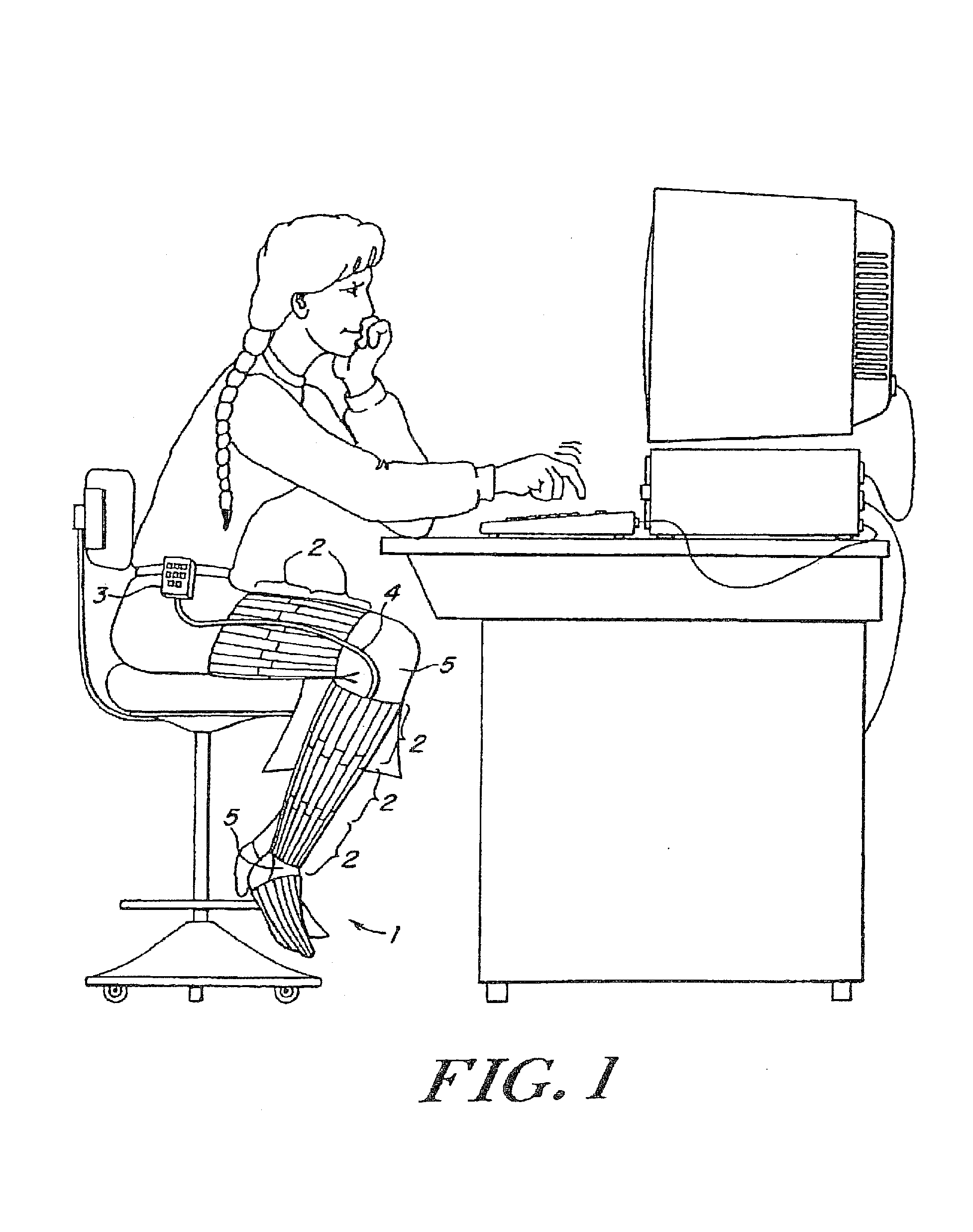
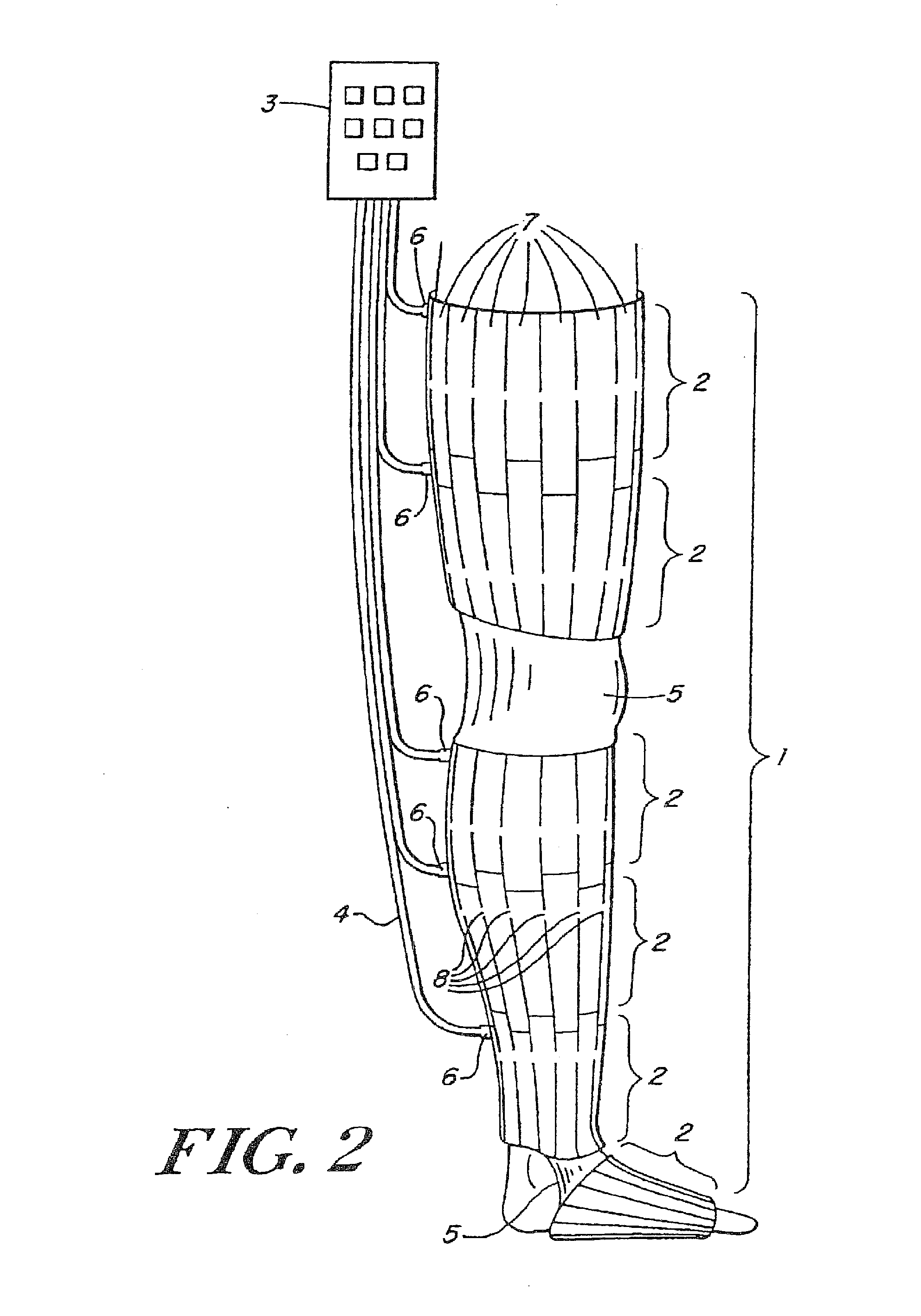
[0087]In the following, an embodiment of the present invention will be described for use on the leg of an individual. However, it i...


PUM


Abstract

An automatic portable ambulant miniaturized system for applying pneumatic pressure to a body limb including a portable ambulant hand-held fluid source unit, a conduit for delivering fluid generated by the unit, a pressure accumulator, and a pressure sleeve coupled to the conduit and adapted to envelop a body limb. The pressure sleeve contains one or more individually inflatable cells, each cell being subdivided into two or more longitudinally extending confluent intra-cell compartments along the axis of the body limb. The intra-cell compartments are inflated and deflated essentially simultaneously by the portable fluid source unit. The pressure accumulator can be flexibly tethered to and pneumatically connected to the fluid source unit, but not integral thereof. The pressure accumulator can also be integral with the pressure sleeve.

Description

CROSS-REFERENCE TO RELATED US PATENT APPLICATIONS[0001]This application is a continuation-in-part of U.S. patent application Ser. No. 09 / 941,909, filed on Aug. 29, 2001 now U.S. Pat. No. 7,063,676; which is a continuation application of U.S. patent application Ser. No. 09 / 413,968, filed Oct. 7, 1999 now U.S. Pat. No. 6,494,852; which is a continuation-in-part of U.S. patent application Ser. No. 09 / 038,157, filed on Mar. 11, 1998 now U.S. Pat. No. 6,478,757 and a continuation-in-part of U.S. patent application Ser. No. 09 / 375,083, filed on Aug. 16, 1999 now U.S. Pat. No. 6,447,467. The entire contents of U.S. patent application Ser. Nos. 09 / 941,909; 09 / 413,968; 09 / 038,157; and 09 / 375,083 are hereby incorporated by reference.PRIORITY INFORMATION[0002]This application claims priority under 35 U.S.C. §119 to U.S. Provisional Patent Application Ser. No. 60 / 424,288, which was filed on Nov. 6, 2002. The entire contents of U.S. Provisional Patent Application Ser. No. 60 / 424,288 are hereby i...

Claims


Application Information

Patent Timeline
Patent Type & Authority Patents(United States)
IPC IPC(8): A61H7/00
CPCA61H9/0078A61H2201/165A61H2205/10A61H2201/5071A61H2201/5007
Inventor BARAK, JACOBGELBART, SARIT DIMIRFABIAN, AMIRNIZAN, YAAKOV
Owner ZIMMER SURGICAL
Why Eureka
Try Eureka