Check patentability & draft patents in minutes with Patsnap Eureka AI!

Look loop circuit and method having improved lock time

a loop circuit and look technology, applied in the field of lock loop circuits, can solve the problems of increasing power consumption and noise of the pll circuit, and achieve the effect of improving the lock time and nois

Active Publication Date: 2009-09-29
NXP USA INC
View PDF6 Cites 7 Cited by
  • Summary
  • Abstract
  • Description
  • Claims
  • Application Information

AI Technical Summary

Problems solved by technology

In addition, the first and second capacitors 112, 114 are known to leak current to ground, which increases power consumption and noise of the PLL circuit 100.

Method used


Image

  • Look loop circuit and method having improved lock time
  • Look loop circuit and method having improved lock time
  • Look loop circuit and method having improved lock time

Examples


Embodiment Construction

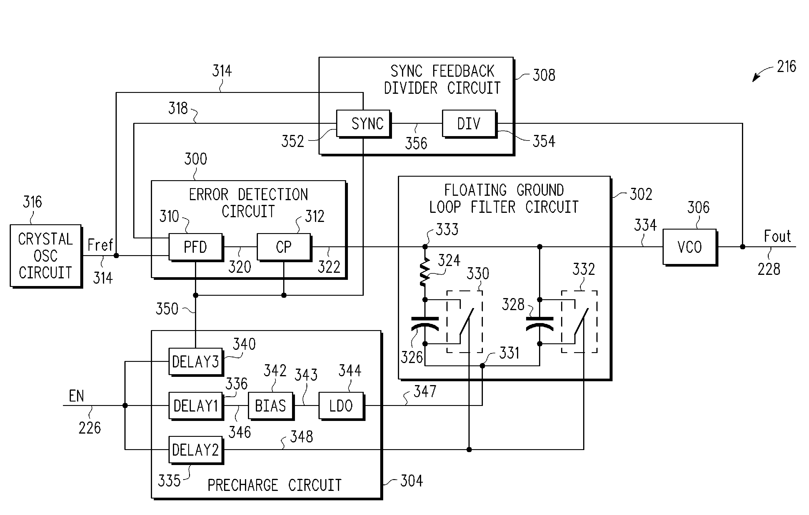
[0022]In one example, a lock loop circuit includes a floating ground loop filter circuit and a precharge circuit. The floating ground loop filter circuit includes at least one capacitive element. The floating ground loop filter circuit provides a steering signal for a controllable oscillator circuit in response to a precharge signal. The precharge circuit provides the precharge signal in response to lock loop enable information. The precharge circuit controls the floating ground loop filter to bypass the capacitive element for a period of time in response to the lock loop enable information. A related method is also disclosed.

[0023]The circuit and method provide, among other advantages, an output signal having a frequency and phase that is locked to a reference signal faster than conventional lock loop circuits and methods. In addition, the floating loop ground filter reduces leakage current to ground, which reduces power consumption and noise of the lock loop circuit. Other advanta...


PUM


Abstract

A lock loop circuit (230) includes a floating ground loop filter circuit (302) and a precharge circuit (304). The floating ground loop filter circuit includes at least one capacitive element (326, 328). The floating ground loop filter circuit provides a steering signal (334) for a controllable oscillator circuit (306) in response to a precharge signal (347). The precharge circuit provides the precharge signal in response to lock loop enable information (226). The precharge circuit controls the floating ground loop filter to bypass the at least one capacitive element for a period of time (606) in response to the lock loop enable information.

Description

CROSS-REFERENCE TO RELATED APPLICATION[0001]This application is related to co-pending application entitled “AUTOMATIC CALIBRATION LOCK LOOP CIRCUIT AND METHOD HAVING IMPROVED LOCK TIME,” filed on even date, having Ser. No. 12 / 042,216, inventors David M. Schlueter and Michael C. Doll, owned by instant Assignee and is incorporated herein by reference in its entirety.BACKGROUND[0002]1. Field[0003]The present disclosure generally relates to lock loop circuits, and more particularly, to lock loop circuits having a reduced time required to lock frequency and phase.[0004]2. Related Art[0005]Lock loop circuits such as phase lock loop (PLL) circuits provide an output signal having a frequency and phase that is locked to a reference signal. More specifically, PLL circuits use feedback to adjust the output signal so that the frequency and phase of the output signal match the reference signal.[0006]As known in the art, PLL circuits are used in many applications such as radio, telecommunications...

Claims


Application Information

Patent Timeline
Patent Type & Authority Patents(United States)
IPC IPC(8): H03L7/10
CPCH03L7/0802H03L7/10H03L7/18H03L7/1075H03L7/107H03L7/101
Inventor SCHLUETER, DAVID M.DOLL, MICHAEL C.
Owner NXP USA INC
Features
  • R&D
  • Intellectual Property
  • Life Sciences
  • Materials
  • Tech Scout
  • Unparalleled Data Quality
  • Higher Quality Content
  • 60% Fewer Hallucinations
Learn More