Phase locked loop circuit with self adjusted tuning

a phase lock loop and self-adjusting technology, applied in the field of integrated circuits, can solve the problems of limiting the tuning range of the pll circuit and the noise sensitivity of the nois

Inactive Publication Date: 2005-10-04
PROMISE TECHNOLOGY
View PDF12 Cites 67 Cited by
  • Summary
  • Abstract
  • Description
  • Claims
  • Application Information

AI Technical Summary

Problems solved by technology

However, as known in the art, a large KVCO increases noise sensitivity of the PLL circuit, and is thus undesirable.
Thus, although desirable for noise sensitivity reduction and stability, a low KVCO limits the tuning range of the PLL circuit.

Method used


Image

  • Phase locked loop circuit with self adjusted tuning
  • Phase locked loop circuit with self adjusted tuning
  • Phase locked loop circuit with self adjusted tuning

Examples


Embodiment Construction

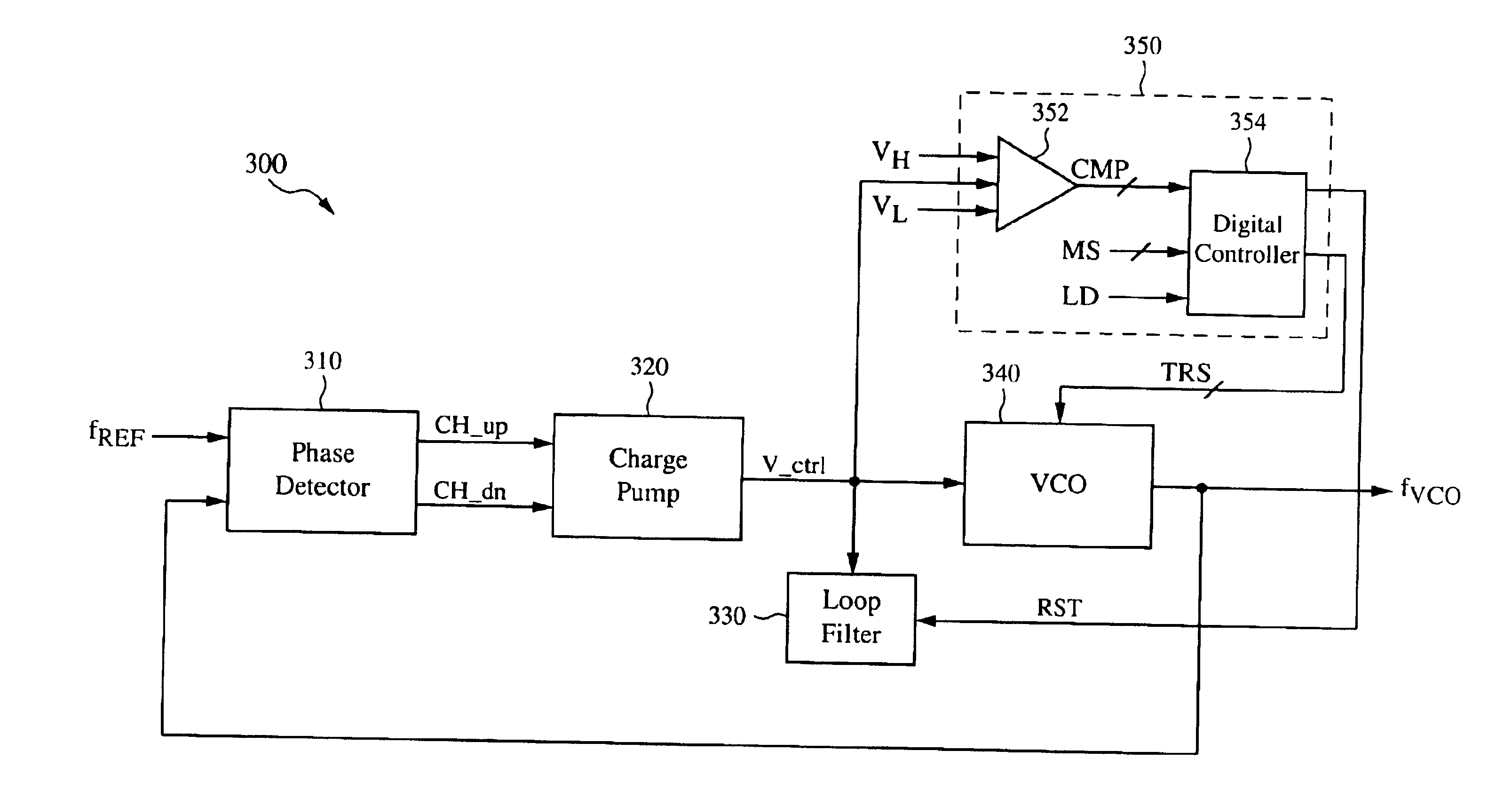
[0019]In accordance with the present invention, a PLL circuit is disclosed that includes a VCO having a resonant circuit with a plurality of individually selectable capacitive elements corresponding to various different tuning ranges, and including a control circuit that selects one of the tuning ranges in response to either externally generated or internally generated control signals. In the following description, exemplary embodiments are described in order to provide a thorough understanding of the present invention. For purposes of explanation, specific nomenclature is set forth to provide a thorough understanding of the present invention. However, it will be apparent to one skilled in the art that these specific details may not be required to practice the present invention. In other instances, well-known circuits and devices are shown in block diagram form to avoid obscuring the present invention unnecessarily. Additionally, the interconnection between circuit elements or block...


PUM


Abstract

A phase-locked loop (PLL) circuit includes a voltage-controlled oscillator (VCO) having a first input to receive a control voltage, one or more second inputs to receive one or more tuning range control signals, and an output to provide an oscillation output signal, a phase detector having inputs to receive the oscillation output signal and a reference signal, a charge pump having an input coupled to the output of the phase detector and having an output to generate the control voltage, a loop filter having an input to receive the control voltage and having a control terminal, and a controller having inputs to receive the control voltage, a high reference voltage, a low reference voltage, and one or more mode signals, and having a first output connected to the control terminal of the loop filter and second outputs to generate the tuning range signals.

Description

FIELD OF INVENTION[0001]The present invention relates generally to integrated circuits and specifically to phase locked loops.DESCRIPTION OF RELATED ART[0002]Phase locked loop (PLL) circuits are well-known circuits that are used, for example, in clock recovery and frequency synthesizing applications. PLL circuits produce an output signal that is synchronized with an input signal, e.g., the frequency of the output signal and the frequency of the input signal maintain a fixed ratio and output signal has a fixed phase relationship with the input signal. FIG. 1 shows a prior art PLL circuit 100 having a phase detector 102, a charge pump and loop filter circuit 104, a voltage-controlled oscillator (VCO) 106, and an optional frequency divider 108. Phase / Frequency detector 102 includes inputs to receive a reference signal fREF from an external source (not shown) and a feedback signal from the VCO 104, and includes an output coupled to the charge pump and loop filter circuit 104. Phase / Freq...

Claims


Application Information

Patent Timeline
Patent Type & Authority Patents(United States)
IPC IPC(8): H03L7/08H03L7/099H03L7/10H03L7/089
CPCH03L7/099H03L7/0995H03L7/10H03L7/0891H03L2207/06
Inventor PHAM, HIEP THE
Owner PROMISE TECHNOLOGY
Why Eureka
Try Eureka