Linear actuator for beds, slatted beds or chairs

a technology of slatted beds and actuators, applied in the direction of seating furniture, rigid chairs, operating chairs, etc., can solve the problems of more expensive connection of simple pipes or rods, transmission of gear wheels, etc., and achieve the effect of correspondingly simple manual control

Inactive Publication Date: 2009-10-06
LINAK AS
View PDF5 Cites 75 Cited by
  • Summary
  • Abstract
  • Description
  • Claims
  • Application Information

AI Technical Summary

Benefits of technology

[0007]This is achieved according to the invention in that the two spindles are rotational interconnected and are driven by a common motor. The invention thus departs from the idea that this form of actuator mu

Problems solved by technology

A gear wheel transmission, however, is more e

Method used


Image

  • Linear actuator for beds, slatted beds or chairs
  • Linear actuator for beds, slatted beds or chairs
  • Linear actuator for beds, slatted beds or chairs

Examples


Embodiment Construction

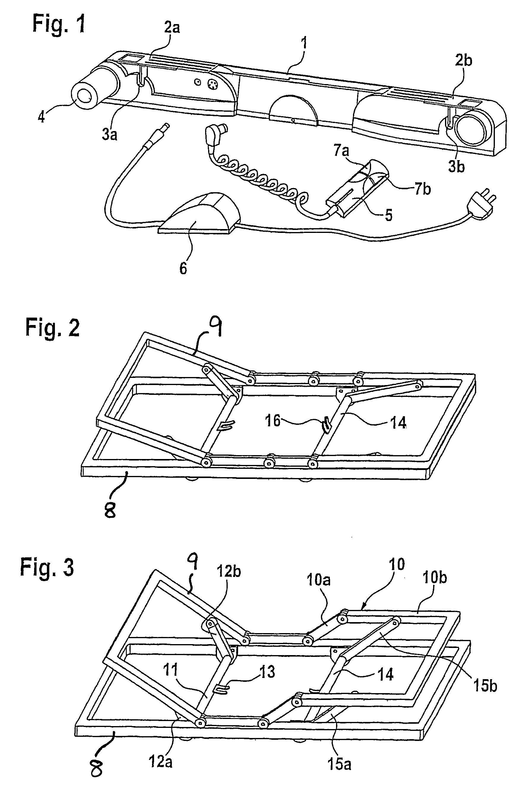
[0023]As will appear from FIG. 1 of the drawings, the actuator includes an elongate cabinet 1 with a cover 2a, 2b which is displaceable from the ends and gives access to a transverse shaft opening 3a, 3b. At one end of the cabinet, the motor is provided in a motor housing 4 arranged perpendicularly from the cabinet. The cabinet has ports for the connection of a hand control 5 and a transformer 6. Owing to its simple structure, the hand control need only be equipped with two operating keys 7a, 7b, viz. one for effecting the raising function and one for the lowering section. The control may also be simplified by allowing the motor current to pass through the hand control in contrast to more sophisticated controls where a separate lower control voltage is used.

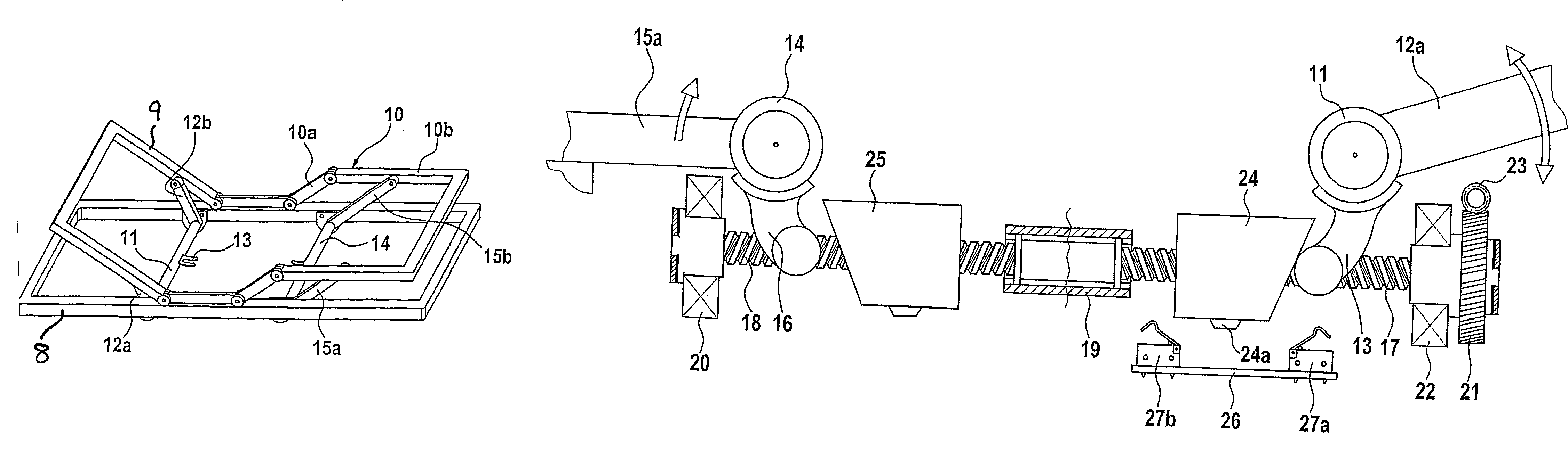
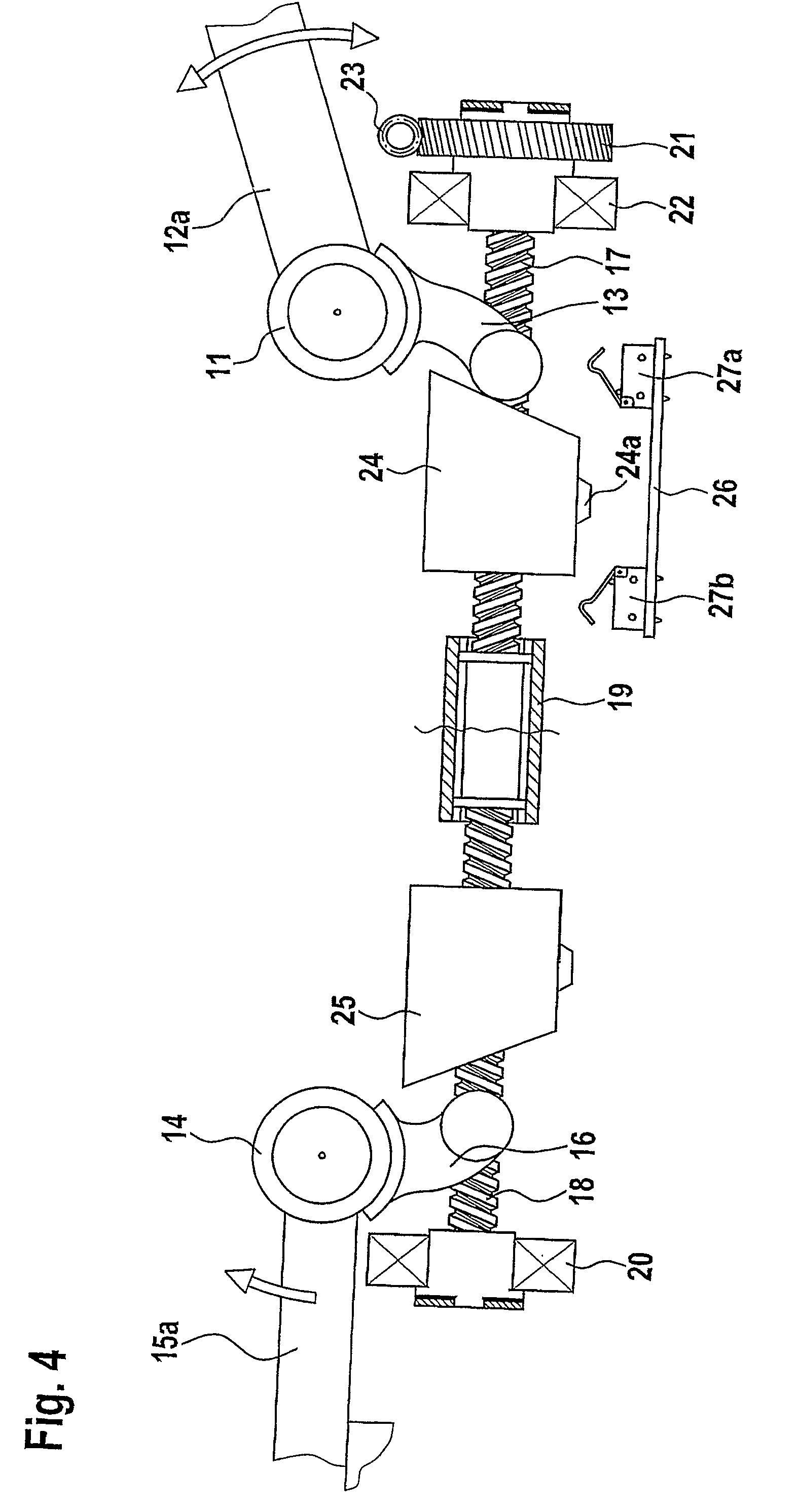
[0024]As will appear from FIGS. 2 and 3, the mattress support includes an circumferential frame 8 which mounts a backrest section 9 and a legrest section 10 which are articulated 10a, 10b. A transverse shaft 11 with a rod 12a, 12...


PUM


Abstract

An actuator for beds, slatted beds or chairs of the type accommodating, in a cabinet, two drive units based on a spindle and a spindle nut configured as an adjustment element, cooperating with an arm of a rotary shaft for a backrest section and a legrest section, respectively, in the bed, the mattress support or the chair. The two spindles are rotational interconnected and are driven by a common reversible electric motor. By having just one motor and one transmissions, as well as no switching mechanism between the two spindles, a simple and inexpensive structure is provided.

Description

BACKGROUND OF THE INVENTION[0001]1. Field of the Invention[0002]The present invention relates to a linear actuator for beds, slatted beds or chairs and to a bed, a mattress support or a chair which includes the linear actuator.[0003]2. The Prior Art[0004]Adjustment of backrest and legrest sections of beds on the basis of electric motors has been well-known for years with respect to hospital and nursing beds. The implementation in beds for domestic use gathered momentum only with the development of the type of actuators which is described in, e.g., WO 89 / 10715 to Dewert Antriebs- und Systemtechnik and DE 38 42 078 to Dietmar Koch. These actuators are based on two individual drive mechanisms driven by their respective electric motors and mounted separately at their respective ends of a common cabinet.[0005]The structure disclosed in WO 03 / 055359 to Cimosys departs from the idea of having a motor for each drive mechanism. Here, there is a common motor with coupling mechanisms so that t...

Claims


Application Information

Patent Timeline
IPC IPC(8): A61G7/015A61G7/05A47C20/08
CPCA47C20/08A47C20/041
Inventor NIELSEN, JENS J.KLINKE, NORBERT
Owner LINAK AS
Why Eureka
Try Eureka