Electric motor assembly

a technology of electric motors and parts, applied in the direction of dynamo-electric machines, magnetic circuit rotating parts, magnetic circuit shapes/forms/construction, etc., to achieve the effect of reducing the total length of the motor, reducing the cost of the motor, and reducing the siz

Active Publication Date: 2014-01-02
IN MOTION TECH PTY LTD
View PDF5 Cites 3 Cited by
  • Summary
  • Abstract
  • Description
  • Claims
  • Application Information

AI Technical Summary

Benefits of technology

[0008]Advantageously, the motor of the present invention may be constructed without a central shaft, resulting in a simplified motor and cost savings.
[0030]Preferably, the stator is made of a metal thereby providing a magnetic attraction between the one or more permanent magnets on the first rotor face and the stator to retain the rotor, bearing assembly and stator in place.

Problems solved by technology

This is difficult to do with a radial flux motor due to the requirement that the two cylinders are held concentric and thus keeping the air gap between the cylinders at a constant thickness.

Method used


Image

  • Electric motor assembly
  • Electric motor assembly
  • Electric motor assembly

Examples


Embodiment Construction

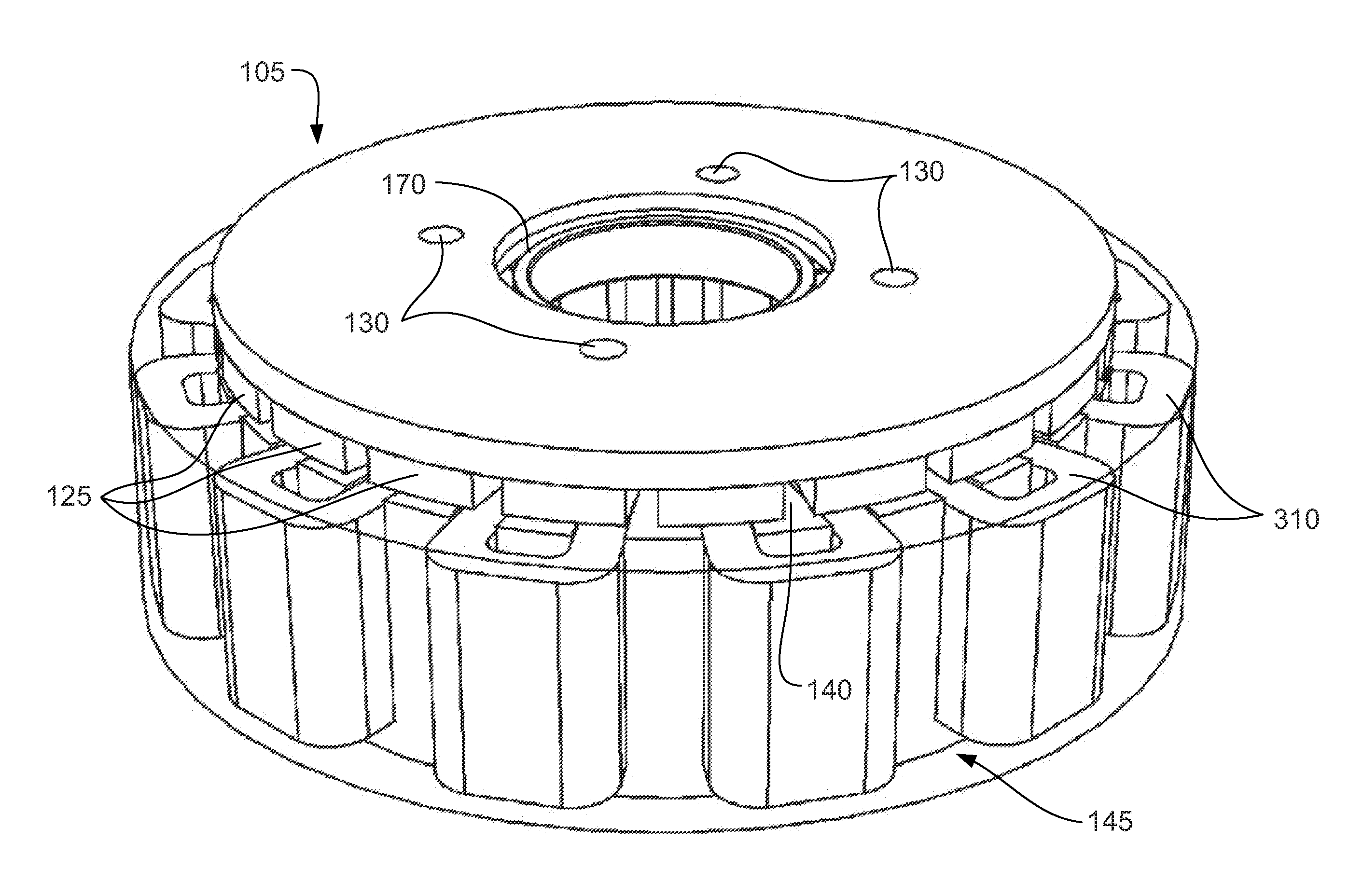
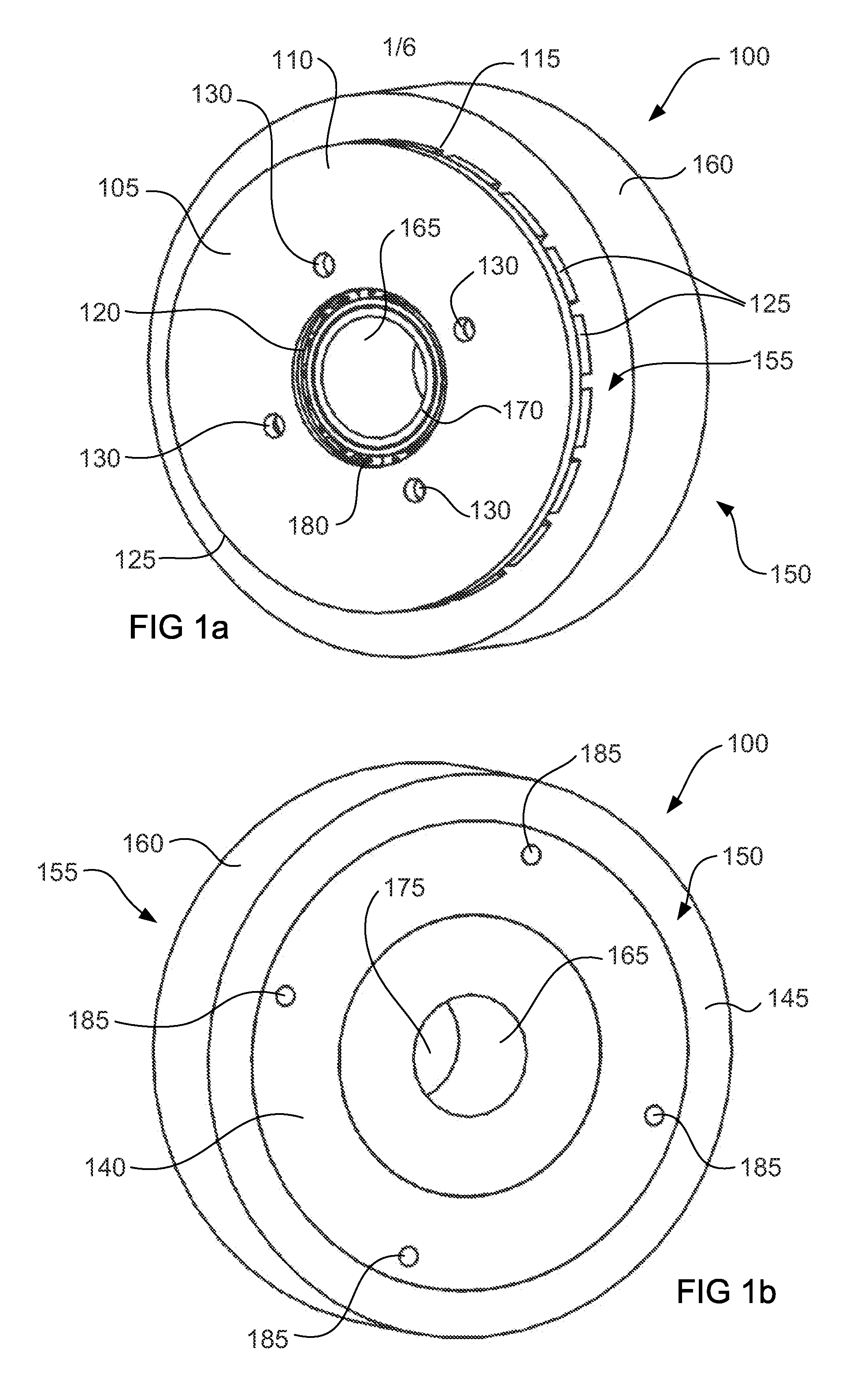
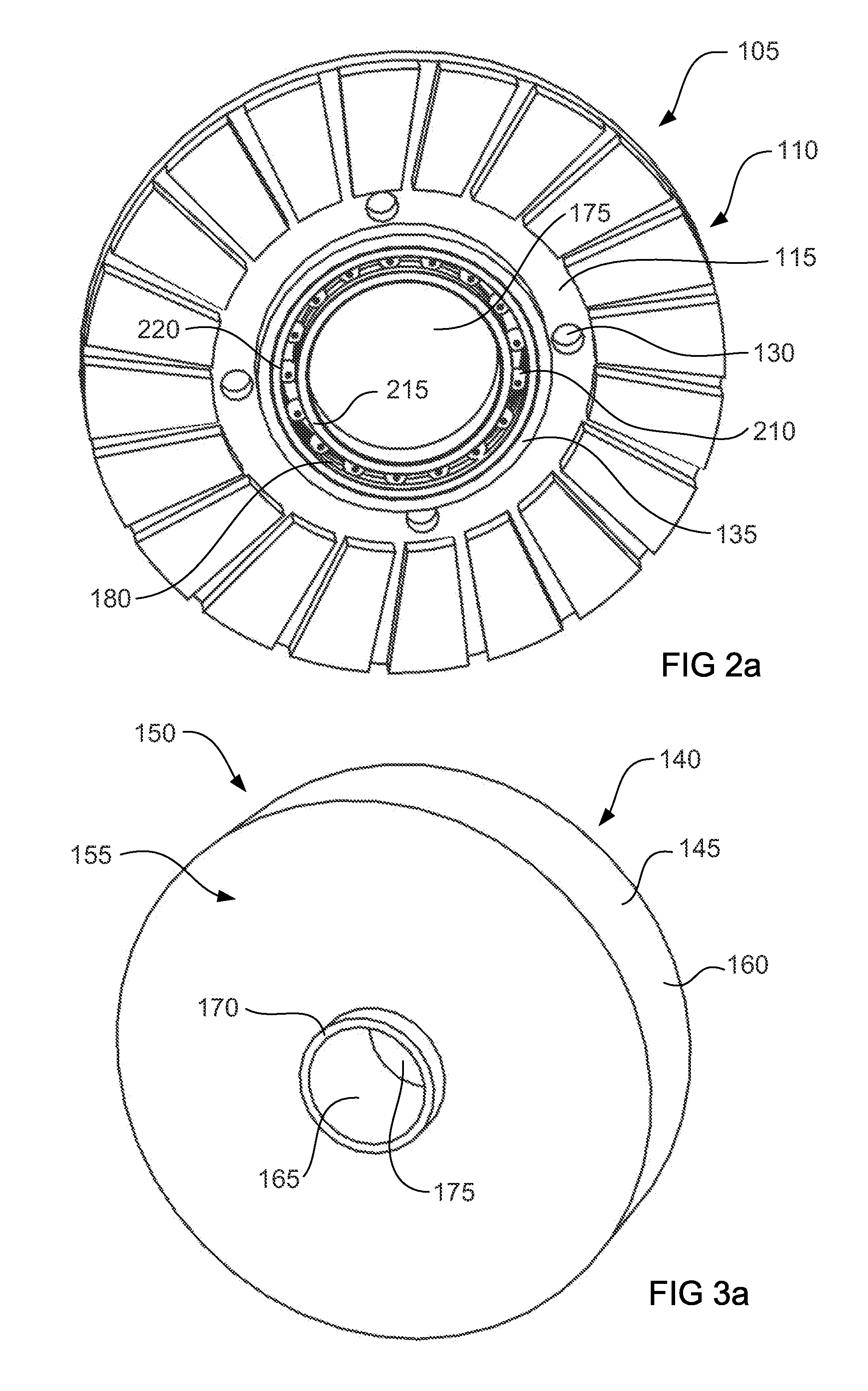
[0047]FIGS. 1a and 1b show a front perspective view and rear perspective view of an axial flux electric flux motor 100 according to the invention. The motor 100 includes a rotor 105, a stator 140 which is housed in a potting material 145 and a bearing assembly 180 which is disposed between the rotor 105 and the stator 140. The rotor 105 is an annular ring having an aperture 175 therethrough. The rotor 105 includes an upper face 110, a lower face 115 and inner wall 120 and an outer wall 125. Located on the lower face 115 is a plurality of magnets 125. The magnets 125 are preferably composed of Neodymium Iron Boron (NdFeB) material, however alternative materials such as Samarium Cobalt or Ferrite will also suffice. Also included on the rotor 105 are rotor mounting apertures 130 and a primary bearing locator 135 (more clearly shown in FIG. 2a). The stator 140 is retained within a potting material 145 which envelops the stator 140 so that the stator 140 is not damaged during operation o...


PUM


Abstract

An axial flux electric motor is disclosed. The motor includes a rotor having a first rotor face, a second rotor face, a primary bearing locator on the first rotor face and one or more permanent magnets mounted to the first rotor face. Also included is a stator having a first stator face, a second stator face, a secondary bearing locator on the first stator face, a stator winding having one or more conductors and a connector for connection of the stator winding to a power source. A bearing assembly is also provided and positioned between the first face of the rotor and the first face of the stator for rotationally supporting movement of the rotor relative to the stator, the bearing assembly axially displacing the rotor from the stator to provide an air gap therebetween. The bearing assembly is engaged by the primary and secondary bearing locators to correctly position the bearing assembly.

Description

FIELD OF THE INVENTION [0001]The present invention relates generally to electric motors, and in particular to an axial flux, brushless direct current (DC) motor.BACKGROUND OF THE INVENTION[0002]Brushless motors offer an advantage over conventional brushed motors since there is no need for the brushes to make mechanical contact with electrical contacts on the rotor. The common configuration for a brushless DC motors is radial-flux, which is composed from two cylinders, a cylindrical stator and a cylindrical rotor (having an axial shaft), with a cylindrical air gap in between and in which the flux travels across the air gap in a direction that is radial to the shaft on the rotor.[0003]In order to hold the two cylinders concentric and thus keep the air gap constant thickness in a radial flux motor, it is necessary to support the shaft at each end of the motor.[0004]Given that many applications which are mechanically powered by a brushless DC motor do not intrinsically require a shaft, ...

Claims


Application Information

Patent Timeline
Patent Type & Authority Applications(United States)
IPC IPC(8): H02K5/167
CPCH02K5/1675H02K21/24H02K1/28H02K7/088H02K7/1008
Inventor CAMILLERI, STEVENTURNER, MATTHEW
Owner IN MOTION TECH PTY LTD
Why Eureka
Try Eureka