Clip for a display

a technology for a display and a clip is applied in the field of clip devices, which can solve the problems of cumbersome manner of holding the foam board in place, difficult to work with foam boards, and difficulty in easy attachment to the display tower, and achieves the effects of convenient manufacturing, strong and flexible, and unitary construction

Inactive Publication Date: 2009-10-06
CONWAY JAMES F
View PDF11 Cites 50 Cited by
  • Summary
  • Abstract
  • Description
  • Claims
  • Application Information

AI Technical Summary

Benefits of technology

[0008]A further object of the present invention is to provide a clip which is of simple construction and design, is inexpensive, and which can be easily employed with highly reliable results.
[0009]Another object of the present invention is to provide a clip that is easy to use and may be moved or positioned along a panel and a display device.
[0010]A still further object of the present invention is to provide a clip that can be secured to and released from a post, a rod, or a pole.
[0011]A further object of the present invention is to provide a clip that may be used to prepare and construct a display.
[0012]Another object of the present invention is to provide a clip that is strong and flexible and has unitary construction.
[0013]Another object of the present invention is to provide a clip that may be easily manufactured and may be disposable.

Problems solved by technology

However, foam board is difficult to work with, needs to be replaced, and is difficult to easily secure to the display tower.
Further, the manner in which foam board is held in place is cumbersome.

Method used


Image

  • Clip for a display
  • Clip for a display
  • Clip for a display

Examples


Embodiment Construction

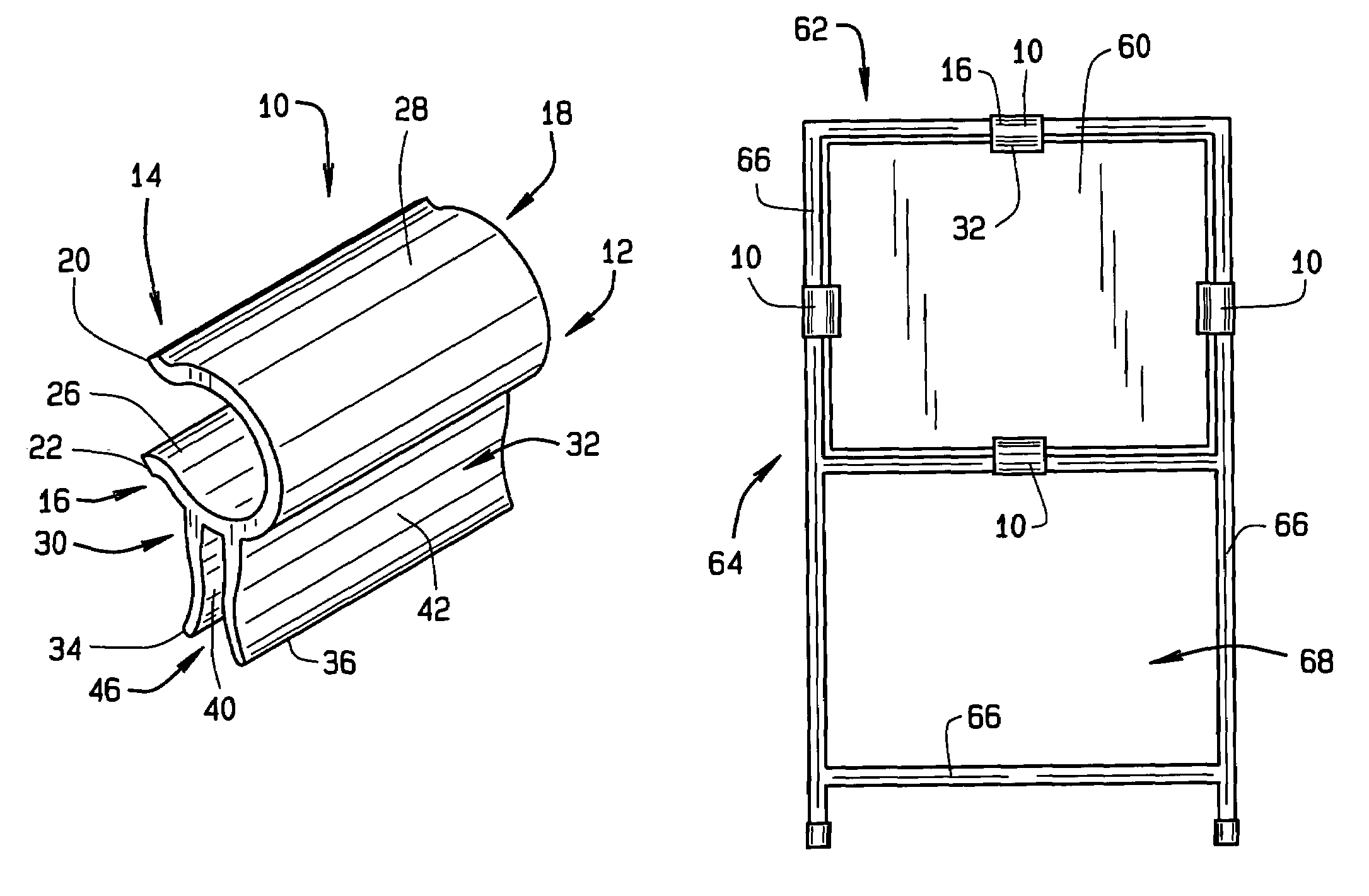
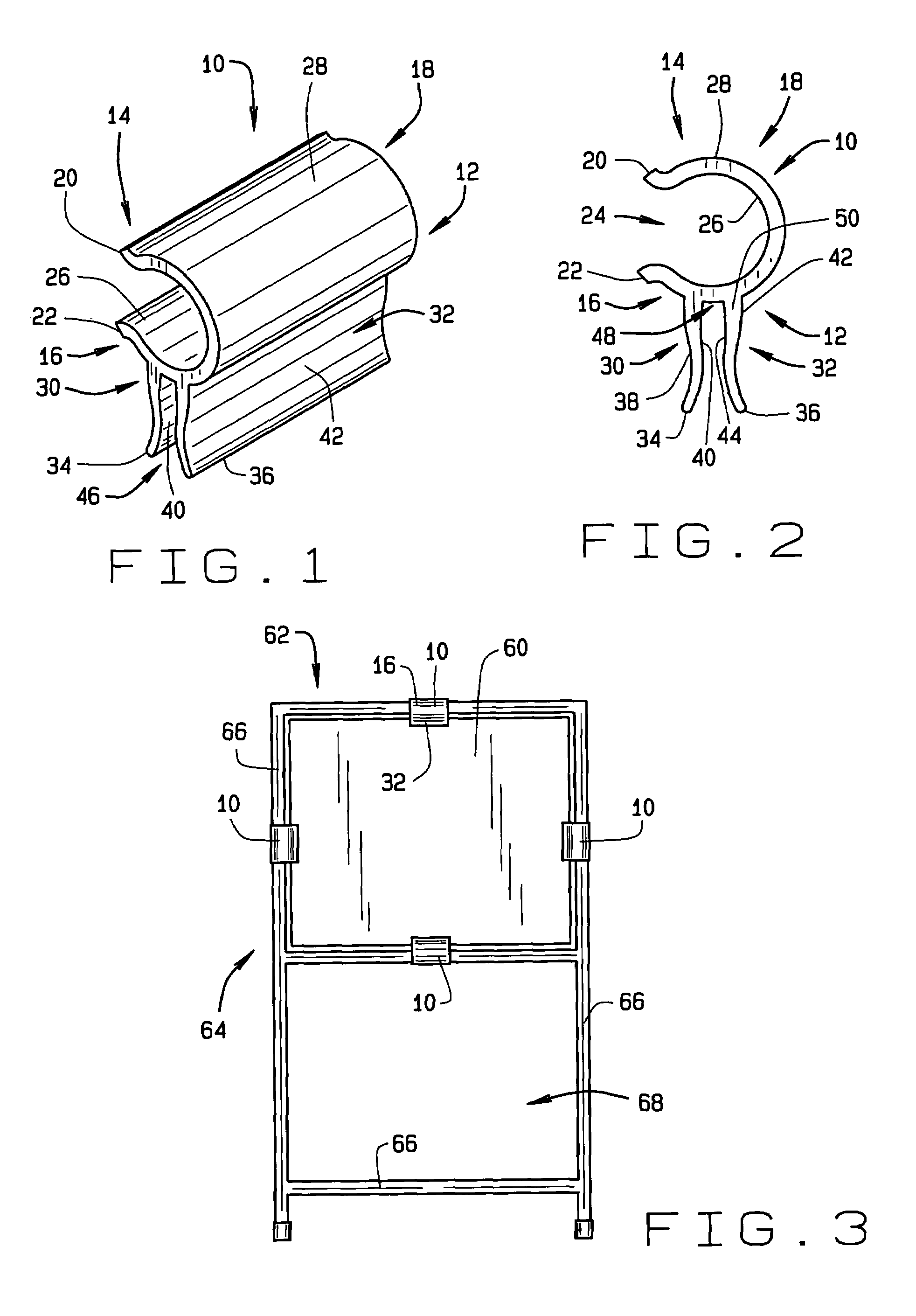
[0021]Referring now to the drawings, wherein like numbers refer to like items, number 10 identifies a preferred embodiment of a clip constructed according to the present invention. With reference now to FIGS. 1 and 2, the clip 10 comprises a unitary body 12 having a first pair of opposing arms 14 and 16 and an intermediate section 18. The intermediate section 18 is arcuate or rounded in shape. The arms 14 and 16 and the intermediate section 18 form a generally C-shaped cross-section. The arms 14 and 16 have opposing end portions 20 and 22, respectively. The end portions 20 and 22 are spaced apart from each other to form a mouth or an opening 24 to allow a rod or pipe (not shown) to pass there through as will be discussed more fully herein. The end portions 20 and 22 are flared outwardly from the respective opposing arms 14 and 16. The clip 10 has an interior surface 26 and an exterior surface 28. The interior surface 26 is adapted to engage or surround a rod or pipe for holding the ...


PUM


Abstract

A clip of the present invention comprises a unitary body having an intermediate section and a first pair of opposing arms with each of the arms having an end portion, the body having an interior surface and an exterior surface, a second pair of opposing arms formed on the exterior surface of the body, each of the second pair of opposing arms having an end portion with the second pair of opposing arms being located between one of the first pair of opposing arms and the intermediate section.

Description

BACKGROUND OF THE INVENTION[0001]This invention relates to a clip device, and more particularly, to a clip used in a display device such as a display tower.[0002]Displays or display towers are used in commercial or retail establishments to display merchandise or advertisements for merchandise. Displays are also used for exhibits, booths, and trade shows. Typically these display towers are formed from rods or poles and are assembled to hold cutouts, sheets, or panels formed from foam board. However, foam board is difficult to work with, needs to be replaced, and is difficult to easily secure to the display tower. In particular, if the foam board has an advertisement printed on it and if the ad changes or a new advertisement is needed then new foam board must be used. This requires that the old foam board be removed from the display tower and new foam boards be printed and inserted into the display tower. Further, the manner in which foam board is held in place is cumbersome. Therefor...

Claims


Application Information

Patent Timeline
Patent Type & Authority Patents(United States)
IPC IPC(8): A47B96/06E04C5/16
CPCA47B47/05A47B95/00G09F3/204F16B12/42G09F3/20A47F3/12F16B12/02
Inventor CONWAY, JAMES F.
Owner CONWAY JAMES F
Why Eureka
Try Eureka