Method for optically detecting height of a specimen and charged particle beam apparatus using the same

a technology of optical detection and charge beam, which is applied in the direction of measuring devices, instruments, electric discharge tubes, etc., can solve the problems of inability to perform highly accurate height detection and inability to completely eliminate errors

Active Publication Date: 2009-10-06
HITACHI HIGH-TECH CORP
View PDF13 Cites 8 Cited by
  • Summary
  • Abstract
  • Description
  • Claims
  • Application Information

AI Technical Summary

Benefits of technology

[0011]In view of the foregoing, the present invention relates to an optical height detection method and an electron beam apparatus to which the method is applied, in which the focusing accuracy of the CD-SEM apparatus, a SEM inspection apparatus, and others is improved by reducing detection errors and improving detection accuracy so as to improve the accuracy of the optical height detection method, and throughput of a CD-SEM apparatus or others is improved by reducing the processing time of automatic focus control which is performed based on the detected height according to the optical height detection method.
[0015]An optical height detection method according to the present invention comprises the steps of: projecting two-dimensional slit light to an object from a position diagonally above the object; detecting light of the projected two-dimensional slit light reflected by said object; converting a two-dimensional slit image of the detected two-dimensional slit light into an electrical signal by a two-dimensional area sensor; and eliminating slit parts, in which a detection error is large, from the electrical signal of the converted two-dimensional slit image and detecting the height of said object.
[0016]Moreover, the optical height detection apparatus of the present invention comprises: a projection optical system which projects two-dimensional slit light to the object from a position diagonally above the object; a detection optical system which detects light of the two-dimensional slit light reflected from the object; a two-dimensional area sensor which converts a two-dimensional slit image of the detected two-dimensional slit light into an electrical signal; and height detection means which detects the height of the object by performing a process of eliminating a slit part including large detection error from the electrical signal of the converted two-dimensional slit image.
[0021]According to the present invention, when the height of an object is to be optically detected, two-dimensional slit light is projected to the object from a position diagonally above it, a slit part having a large detection error is eliminated from the electrical signal of the two-dimensional slit image obtained by the reflected light detected by the two-dimensional area sensor, and the height of the object is detected from the shift distance of the slit part other than eliminated ones. Thus, the detection error can be significantly reduced, and highly accurate height detection can be performed. In addition, in an electron beam apparatus which performs focus control through optical height detection, for example, in the case of a CD-SEM apparatus, optical height detection and automatic focus control based on that are performed, and if highly accurate optical height detection can be performed, the processing time of the automatic focus control can be reduced. Therefore, the throughput of the CD-SEM apparatus can be improved. In addition, in the case of a SEM inspection apparatus, focus position control is performed through optical height detection, electron beam images are successively obtained, and comparison test of patterns is performed. Therefore, when the accuracy of the optical height detection is increased, high-quality electron beam images of focused positions can be obtained, and highly reliable inspection can be performed.

Problems solved by technology

Consequently, a detection error 508 occurs, and it has been unable to perform highly accurate height detection.
However, the errors are not completely eliminated.

Method used


Image

  • Method for optically detecting height of a specimen and charged particle beam apparatus using the same
  • Method for optically detecting height of a specimen and charged particle beam apparatus using the same
  • Method for optically detecting height of a specimen and charged particle beam apparatus using the same

Examples


first embodiment

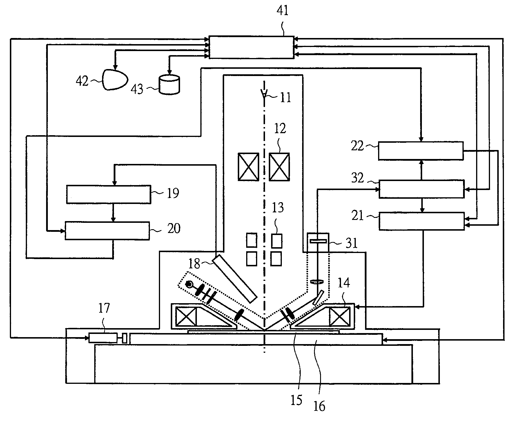
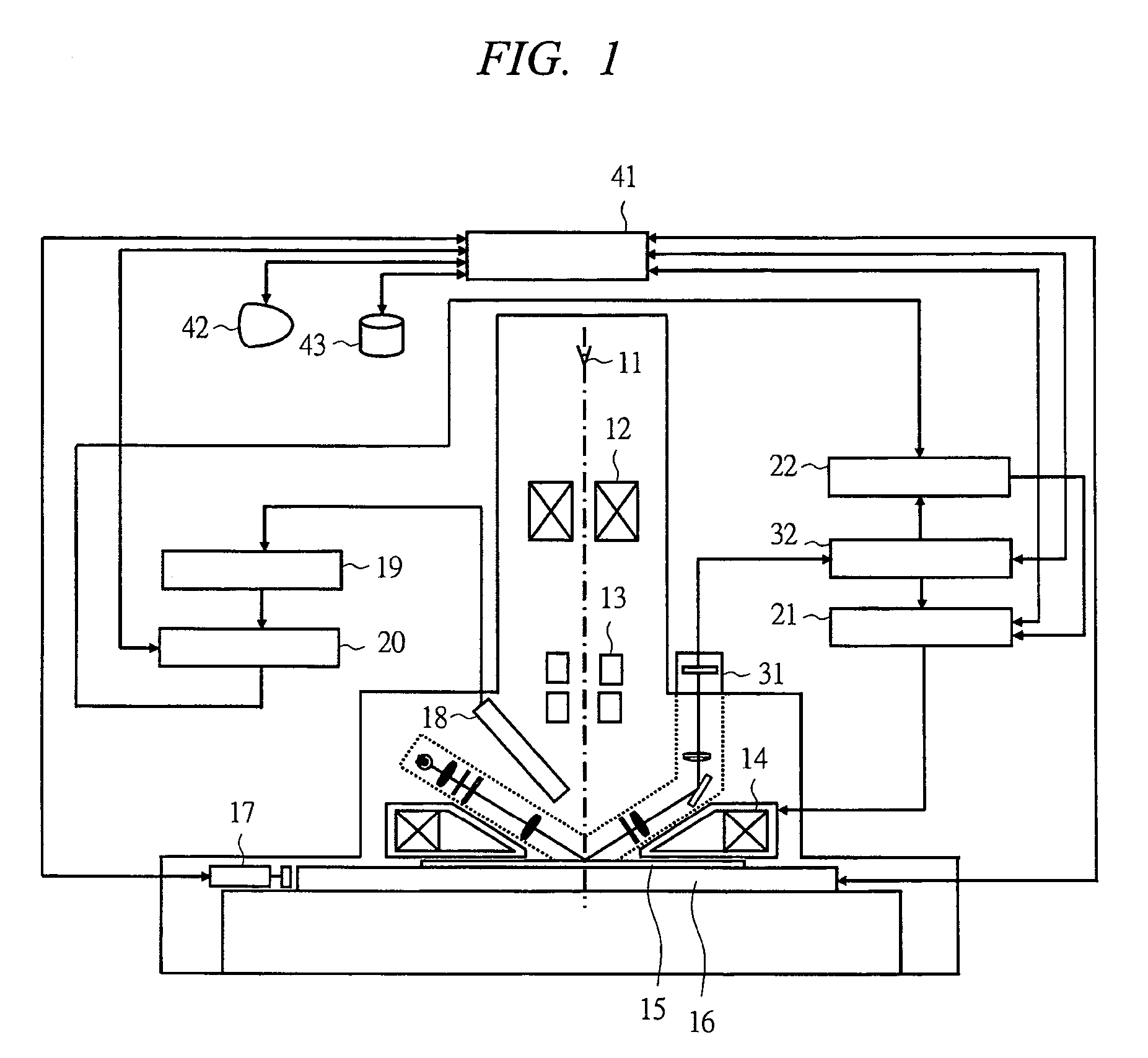
[0056]FIG. 1 is a schematic diagram showing a configuration of a CD-SEM apparatus in a first embodiment of the present invention. The CD-SEM apparatus obtains electron beam images of a measurement object (measured object, object to be measure) 15 by a scanning electron microscope and measures line widths of fine patterns and hole diameters of the measurement object 15 by image processing for condition setting or monitoring of semiconductor manufacturing processes.

[0057]The CD-SEM apparatus comprises: a scanning electron microscope system which obtains electron beam images of the measurement object 15 and performs image processing; a focus control system which performs focusing of the scanning electron microscope; an optical height detection system which detects the height of the measurement object 15; and an overall control system.

[0058]The scanning electron microscope system includes: an electron beam source 11 which emits an electron beam; a condenser lens 12 which converges the e...

second embodiment

[0084]Next, a CD-SEM apparatus in a second embodiment of the present invention will be described with reference to FIGS. 7A to 7C. In this embodiment, the height calculation processing device 32 which calculates the height of an object from a two-dimensional slit image is different from that in the first embodiment in that the slits eliminated as detection errors are the slits having large shift distances with respect to the shift distances of adjacent slits. Other parts of this embodiment are the same as those of the first embodiment.

[0085]In this embodiment, the shift distance of a slit image is calculated for each slit with respect to the detected waveform 129 of each slit part which is the clipped slit part shown in FIG. 4D, the differences between the calculated shift distance and the shift distances of adjacent slits are calculated, the slit part having a calculated difference from the adjacent shift distance larger than a predetermined value is eliminated, and the height of t...

third embodiment

[0091]Next, a CD-SEM apparatus in a third embodiment of the present invention will be described with reference to FIGS. 8A to 8C. In this embodiment, the height calculation processing device 32 which calculates the height of an object from a two-dimensional slit image is different from those of the first embodiment and the second embodiment in that the shift distances of slits are applied to a curved line, and the slit eliminated as a detection error is a slit having a large difference from the curved line.

[0092]In this embodiment, in the slit part clipping process 171 shown in FIG. 7B of the above-described second embodiment, the shift distance of a slit image is calculated for each slit with respect to the detection waveform of each slit part which is a clipped slit part, the calculated shift distance is applied to a curved line respectively in the x direction and y direction for each detection line, the slit part having the large difference from the applied curved line is elimina...


PUM


Abstract

The present invention provides an optical height detection method and electron beam apparatus to which the method is applied, in which the focusing accuracy of the CD-SEM apparatus, a SEM inspection apparatus, and others is improved by reducing detection errors and improving detection accuracy so as to improve the accuracy of the optical height detection method, and throughput of a CD-SEM apparatus or others is improved by reducing the processing time of automatic focus control performed based on the detected height according to the optical height detection method. An optical detection optical system projects two-dimensional slit light to a measurement object from diagonally above it, detects the light reflected by the measurement object, converts a detected two-dimensional slit image into an electrical signal by a two-dimensional area sensor, eliminates slit parts having a large detection error from the electrical signal, and detects the height of the measurement object.

Description

CROSS-REFERENCE TO RELATED APPLICATION[0001]The present application claims priority from Japanese Patent Application No. JP 2005-327190 filed on Nov. 11, 2005, the content of which is hereby incorporated by reference into this application.TECHNICAL FIELD OF THE INVENTION[0002]The present invention relates to a technology for measuring and inspecting an object by a charged particle beam image of the object obtained by irradiating charged particle beam such as an electron beam or ion beam to the object wherein a semiconductor substrate such as a semiconductor wafer serves as a target. In particular, it is suitable for an optical height detection method which optically detects the height of the wafer for focus control of a charged particle beam image and for an electron beam apparatus using the same.BACKGROUND OF THE INVENTION[0003]For example, as the patterns formed on semiconductor wafers are miniaturized, dimension measurement and defect detection by optical measurement and inspecti...

Claims


Application Information

Patent Timeline
Patent Type & Authority Patents(United States)
IPC IPC(8): G01B11/28
CPCG01B11/0608H01J37/20H01J37/21H01J37/265H01J37/28H01J2237/2817H01J2237/20292H01J2237/216H01J2237/2482
Inventor SAITO, KEIYAWATANABE, MASAHIROYOSHITAKE, YASUHIRO
Owner HITACHI HIGH-TECH CORP
Why Eureka
Try Eureka