Substrate holding device

a holding device and substrate technology, applied in the direction of chucks, mechanical equipment, manufacturing tools, etc., can solve the problems of doming deformation, wafer flexure between pin-shaped protrusions, and the inability to accurately record shots, so as to achieve the effect of stabilizing the focusing accuracy between shots

Inactive Publication Date: 2008-09-16
CANON KK
View PDF24 Cites 12 Cited by
  • Summary
  • Abstract
  • Description
  • Claims
  • Application Information

AI Technical Summary

Benefits of technology

The present invention provides a substrate holding chuck with protrusions for supporting a substrate during exposure. The protrusions include pin-shaped protrusions and a circular first peripheral wall portion. The chuck has a first area where the pin-shaped protrusions are arrayed in a circumferential form and a second area where they are arrayed in a grid-like manner. The spacing between the pin-shaped protrusions is a fraction of the size of the exposure viewing angle of an exposure apparatus. This arrangement provides reproducible flexure and stable focusing accuracy between shots.

Problems solved by technology

When this pin chuck is used, three problems ascribable to vacuum-induced deformation arise.
The first problem is wafer flexure that occurs between the pin-shaped protrusions.
The second problem is doming deformation ascribable to wafer flexure that occurs at the portion of the lifting-pin hole 11.
The third problem is lift-up, which occurs for reasons similar to those of the problems above, between the seal wall (14) at the outer circumference of the chuck and the adjacent pins.
However, if the pins are brought closer together by reducing pin spacing in order to reduce flexure between the pins, the amount of flexure decreases but the rate of contact with the underside of the wafer increases, thereby elevating the probability that foreign matter will intrude.
With regard to the second and third problems, the prior art is such that a decline in planarity at the time of vacuum-induced suction becomes conspicuous at the periphery of the hole for the substrate lifting pin near the center of the chuck.
In each of these examples of the prior art, however, leakage at the peripheral wall portion is a problem and various difficulties arise, such as a decline in vacuum pressure and loss of a plane correcting force at the rim of a wafer that exhibits a large amount of curvature.
This results in higher manufacturing cost.

Method used


Image

  • Substrate holding device
  • Substrate holding device
  • Substrate holding device

Examples


Embodiment Construction

[0022]Preferred embodiments of the present invention will now be described in detail in accordance with the accompanying drawings.

Embodiment of an Exposure Apparatus

[0023]An embodiment of the invention will now be described in concrete terms using an example in which a substrate holding device according to the present invention is applied to a demagnifying projection exposure apparatus.

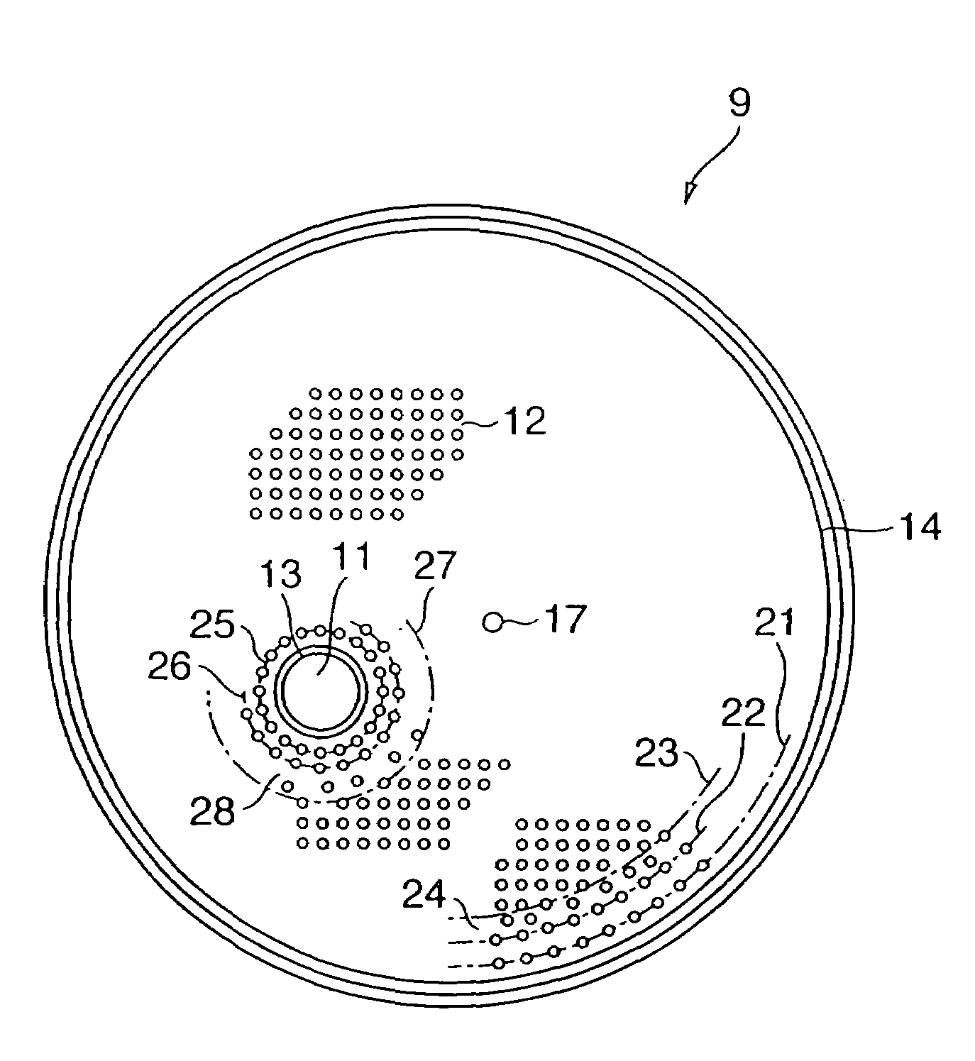
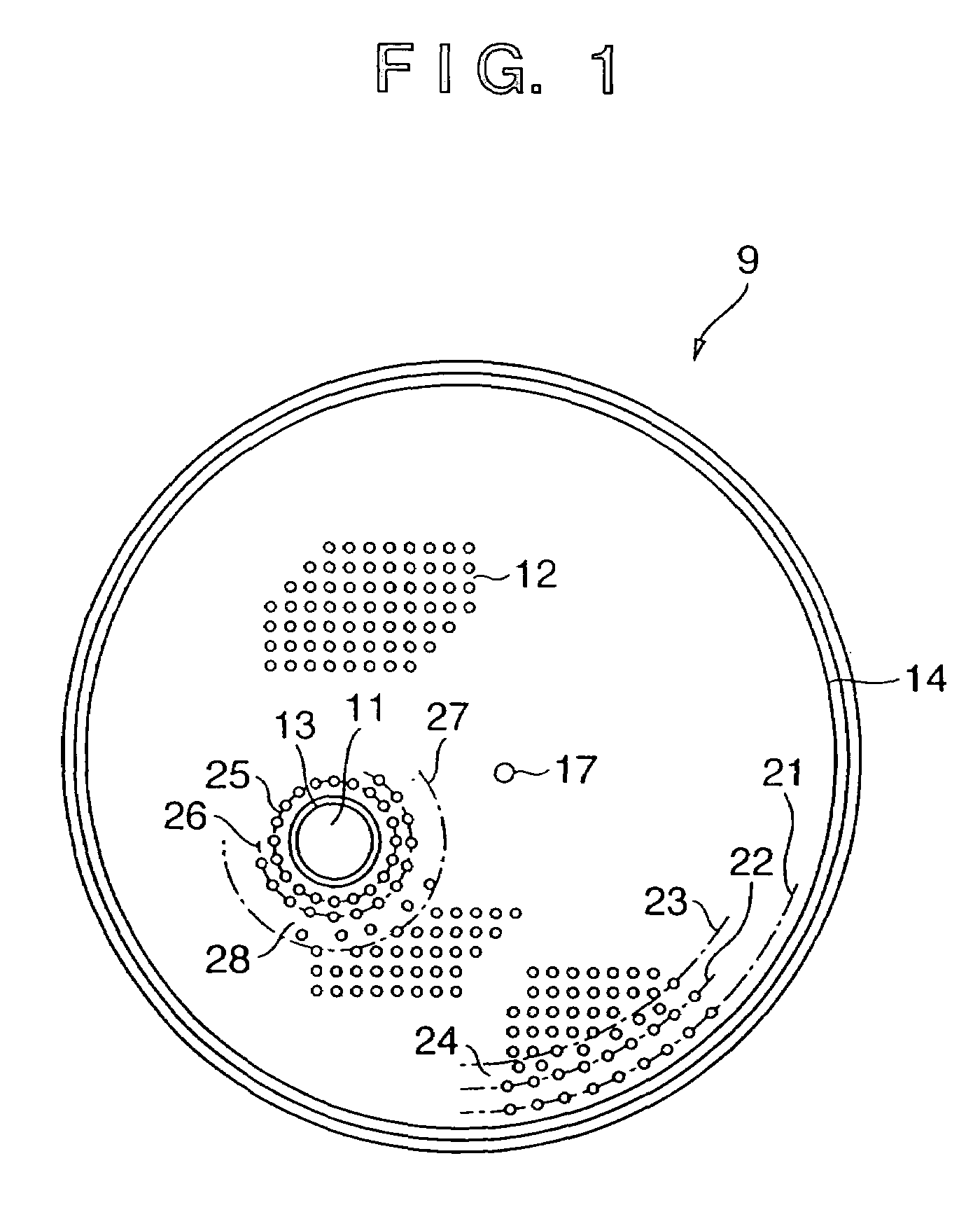
[0024]FIG. 4 is an overall schematic view of an exposure apparatus. As shown in FIG. 4, the exposure apparatus is such that a reticle 2, which is an exposure master, is placed on a reticle stage 4 via a reticle chuck 3. The reticle 2 is irradiated with exposing light guided to it from a light source (not shown) via an illuminating optical system 1. The exposing light that has passed through the reticle 2 is demagnified to, e.g., one-fifth the size by a projection optical system 5 and illuminates a silicon wafer 8, which is the workpiece. A so-called wafer chuck 9, namely a substrate holding device ser...


PUM

PropertyMeasurementUnit
pressureaaaaaaaaaa
areaaaaaaaaaaa
supporting forceaaaaaaaaaa

Abstract

Disclosed is a wafer chuck, which has protrusions for supporting a substrate, for attracting and holding the substrate by negative pressure while the substrate is being supported by the protrusions. The wafer chuck includes pin-shaped protrusions dispersed on a suction side of the chuck, and circular peripheral wall portions disposed in the vicinity of the rim of the supported substrate and in the vicinity of the outer peripheral portion of a lifting hole, respectively. The suction side of the wafer chuck is provided with a first area in which the pin-shaped protrusions are arrayed in a grid-line manner, and a second area in which the pin-shaped protrusions are arrayed in circumferential form. The second area is provided in the vicinity of the peripheral wall portion and peripheral wall portion, and the first area is provided elsewhere.

Description

FIELD OF THE INVENTION[0001]This invention relates to a substrate holding device for holding a substrate serving as a workpiece. More particularly, the invention relates to a substrate holding device used in a semiconductor manufacturing apparatus, a liquid-crystal substrate manufacturing apparatus, a magnetic-head manufacturing apparatus, a micromachine manufacturing apparatus, and the like. Also, the invention relates to an exposure apparatus and a device manufacturing method using such a substrate holding device.BACKGROUND OF THE INVENTION[0002]The growth of the sophisticated information-oriented society in recent years has been accompanied by rapid advances in the manufacture of finer and more highly integrated elements. Lenses of higher numerical apertures are being used in order to deal with the manufacture of finer elements in demagnifying projection exposure systems used in the manufacture of semiconductor devices. Though resolution rises owing to use of higher numerical ape...

Claims


Application Information

Patent Timeline
Patent Type & Authority Patents(United States)
IPC IPC(8): B23B31/30C23C16/00H01L21/683B23Q3/08B25B11/00G11B5/31H01L21/027H01L21/68
CPCB25B11/005Y10T279/11H01L21/68
Inventor MUTO, YASUYOTAKABAYASHI, YUKIO
Owner CANON KK
Why Eureka
Try Eureka