Position detecting circuit and apparatus using the same

a technology of position detection and circuit, applied in the direction of electronic commutators, electric motor control, instruments, etc., can solve the problems of lowering the accuracy of position detection and changing the sensitivity of the hall effect devi

Active Publication Date: 2009-10-06
OLYMPUS CORP
View PDF2 Cites 59 Cited by
  • Summary
  • Abstract
  • Description
  • Claims
  • Application Information

AI Technical Summary

Problems solved by technology

In such a case, since Hall effect device possesses a temperature characteristic, there is a problem that sensitivity of the Hall effect device is changed and its position detecting accuracy is lowered with change in the ambient temperature.

Method used


Image

  • Position detecting circuit and apparatus using the same
  • Position detecting circuit and apparatus using the same
  • Position detecting circuit and apparatus using the same

Examples


Embodiment Construction

[0027]Some embodiments of the position detecting circuit according to the invention and of apparatus to which the same is applied will be described below with reference to the drawings.

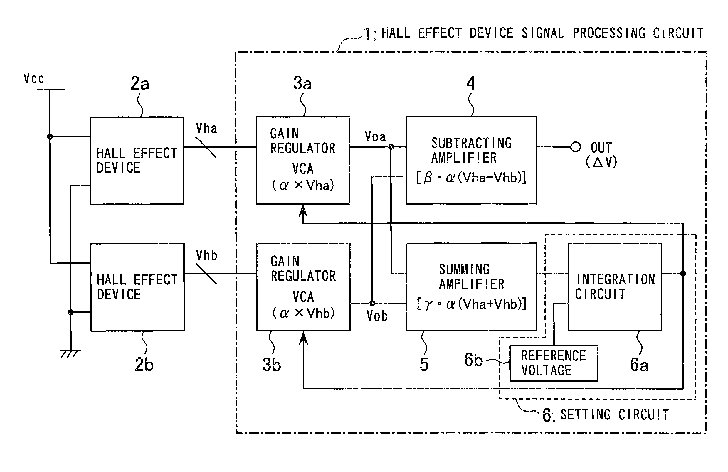
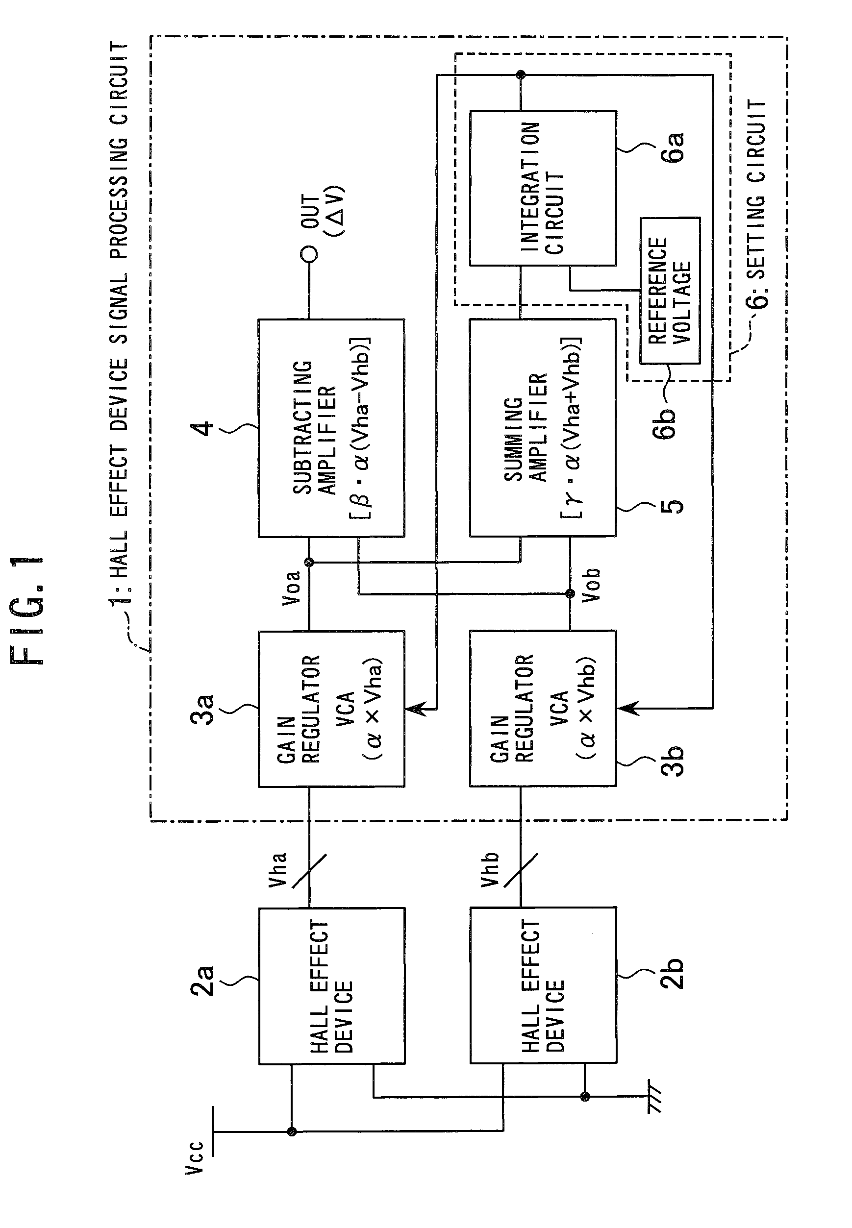
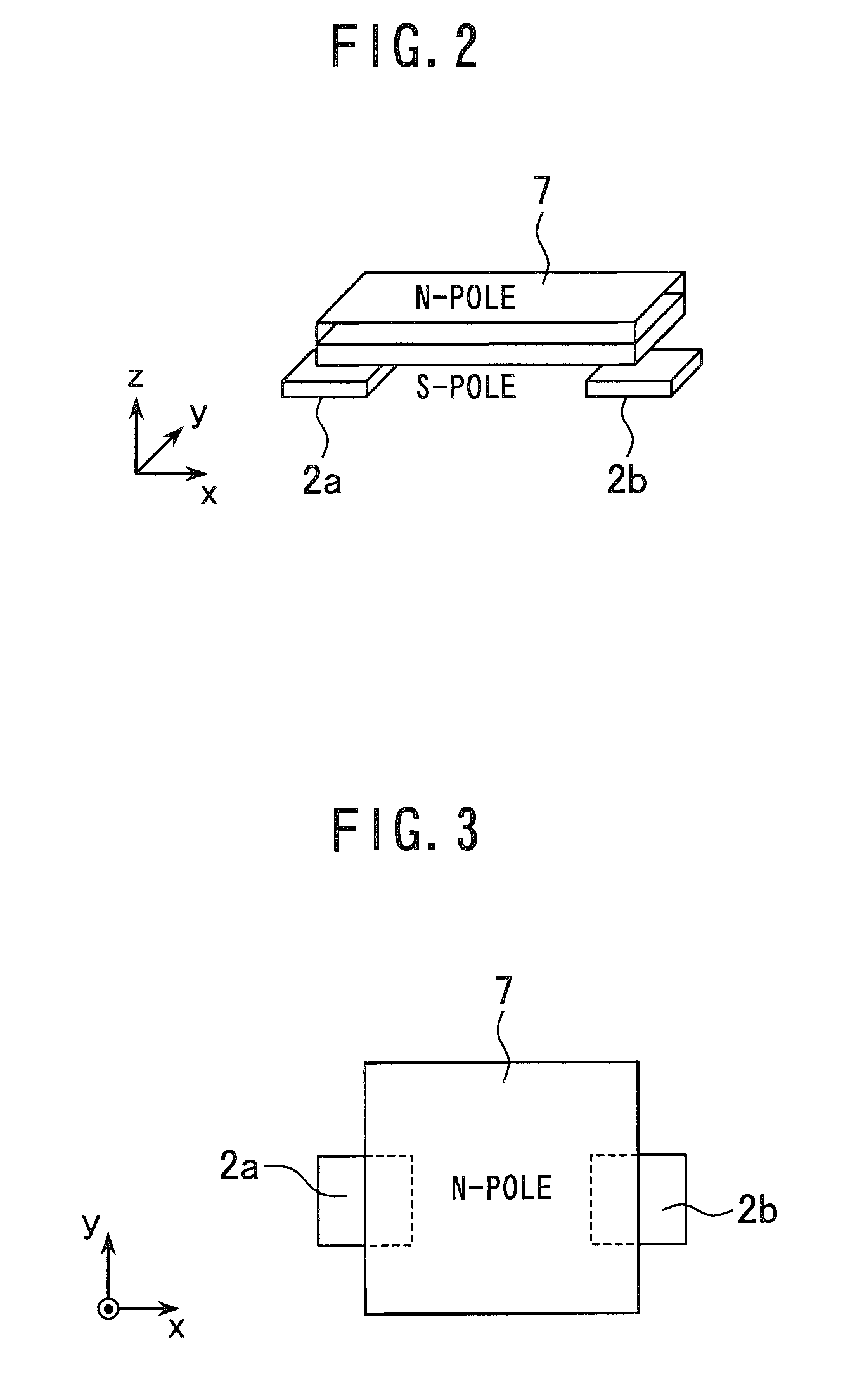
[0028]A first embodiment of the position detecting circuit according to the invention will now be described. FIG. 1 is a block diagram showing construction of the position detecting circuit according to the first embodiment; and FIGS. 2 and 3 are a perspective view and top view of physical disposition of the components for use in detecting position. The construction as shown in the figures will now be described. In this embodiment, Hall effect devices 2a, 2b are used as magnetic field detecting device, VCA 3a, 3b as gain regulator, and a rectangular permanent magnet 7 as a magnetic force generating member. As shown in FIG. 1, the position detecting circuit according to this embodiment includes the Hall effect devices 2a, 2b, and a Hall effect device signal processing circuit 1. Further, the Hall effec...


PUM


Abstract

A position detecting circuit including: a plurality of magnetic field detecting devices discretely disposed for outputting a signal corresponding to a magnetic field strength produced by an oppositely disposed magnetic field generation means; a correction parameter arithmetic section for computing correction parameters for bringing to a predetermined constant value a sum of output from one of the magnetic field detecting devices and an output from another of the magnetic field detecting devices; and a position arithmetic section for computing and outputting a relative position between the magnetic field generation means and the magnetic field detecting devices based on an output difference the between the output from the one magnetic field detecting device and output from the another magnetic field detecting device and the correction parameters.

Description

[0001]This application claims benefit of Japanese Patent Application No. 2007-13269 filed in Japan on Jan. 24, 2007, the contents of which are incorporated by this reference.BACKGROUND OF THE INVENTION[0002]The present invention relates to position detecting circuit for detecting relative position between objects, and relates to apparatus using the position detecting circuit.[0003]Because of their relatively low cost, sensor systems using a permanent magnet and Hall effect device (magnetic field detecting device) are widely used as the system for detecting relative position between objects. In such a case, since Hall effect device possesses a temperature characteristic, there is a problem that sensitivity of the Hall effect device is changed and its position detecting accuracy is lowered with change in the ambient temperature. To solve this problem, Japanese Patent Application Laid-Open hei-7-181557 discloses a temperature correction means composed of a transistor having a temperatu...

Claims


Application Information

Patent Timeline
Patent Type & Authority Patents(United States)
IPC IPC(8): G01C17/38
CPCH02P29/0094H02P6/16H02P29/685
Inventor YAMAZAKI, SUSUMU
Owner OLYMPUS CORP
Why Eureka
Try Eureka