
Method, arrangement and bracket for mounting a rim accessory on a vehicle

a technology for mounting brackets and rim accessories, which is applied in the direction of vehicle components, wheel protection, transportation and packaging, etc., can solve the problems of limited inability to remove the wheel cap without tools, and inability to afford any protection against external influences, etc., to achieve quick and easy mounting of various rim accessories

Inactive Publication Date: 2009-10-13
VOLVO LASTVAGNAR AB
View PDF16 Cites 5 Cited by
  • Summary
  • Abstract
  • Description
  • Claims
  • Application Information

AI Technical Summary

Benefits of technology

[0002]The invention relates to a method and an arrangement for quickly and easily mounting various rim accessories on a vehicle, the vehicle having rims with fasteners for fastening to a wheel hub on a drive wheel or on wheels intended for a trailer.
[0007]It is desirable to provide an arrangement for quick and easy mounting of various rim accessories on a vehicle.
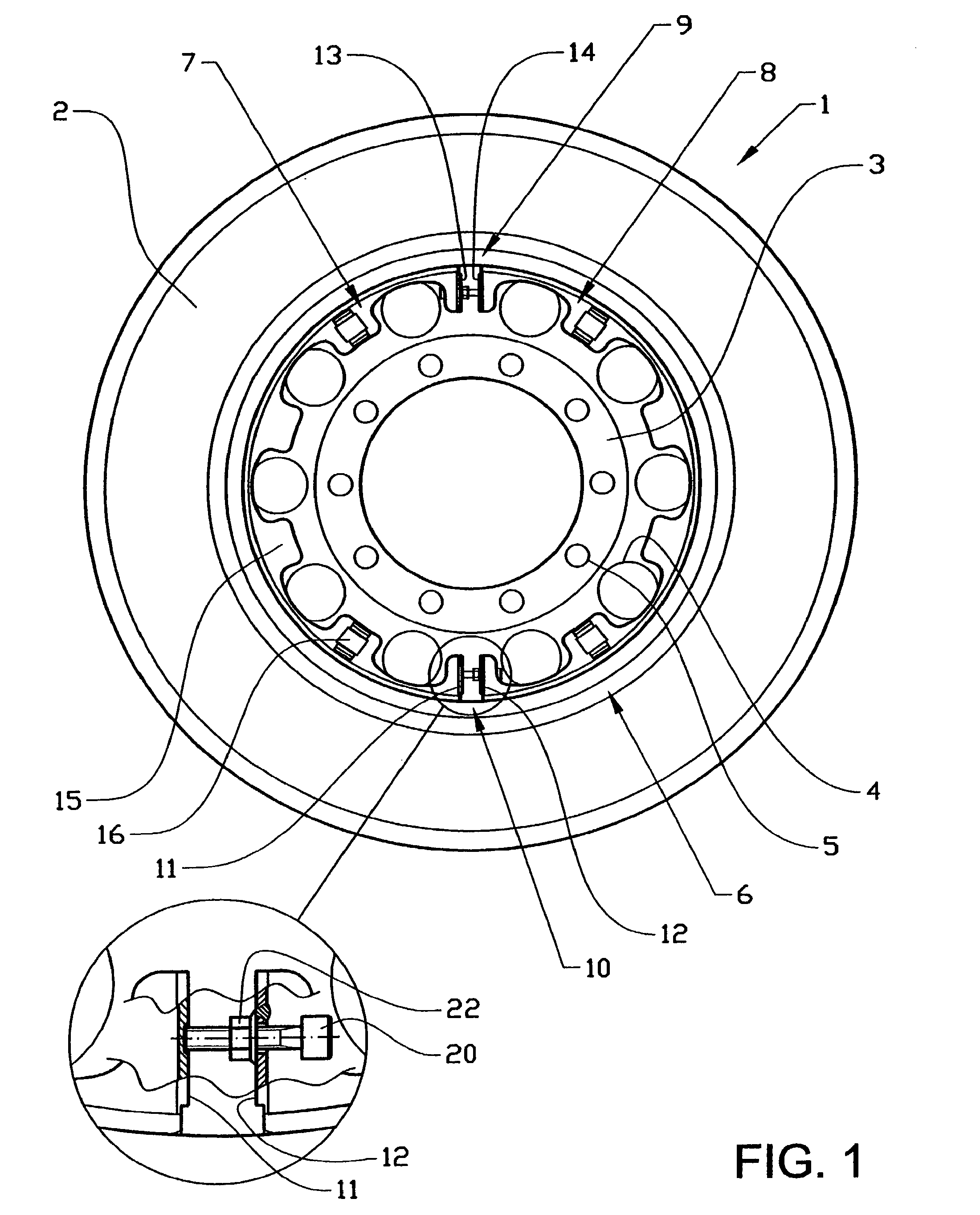
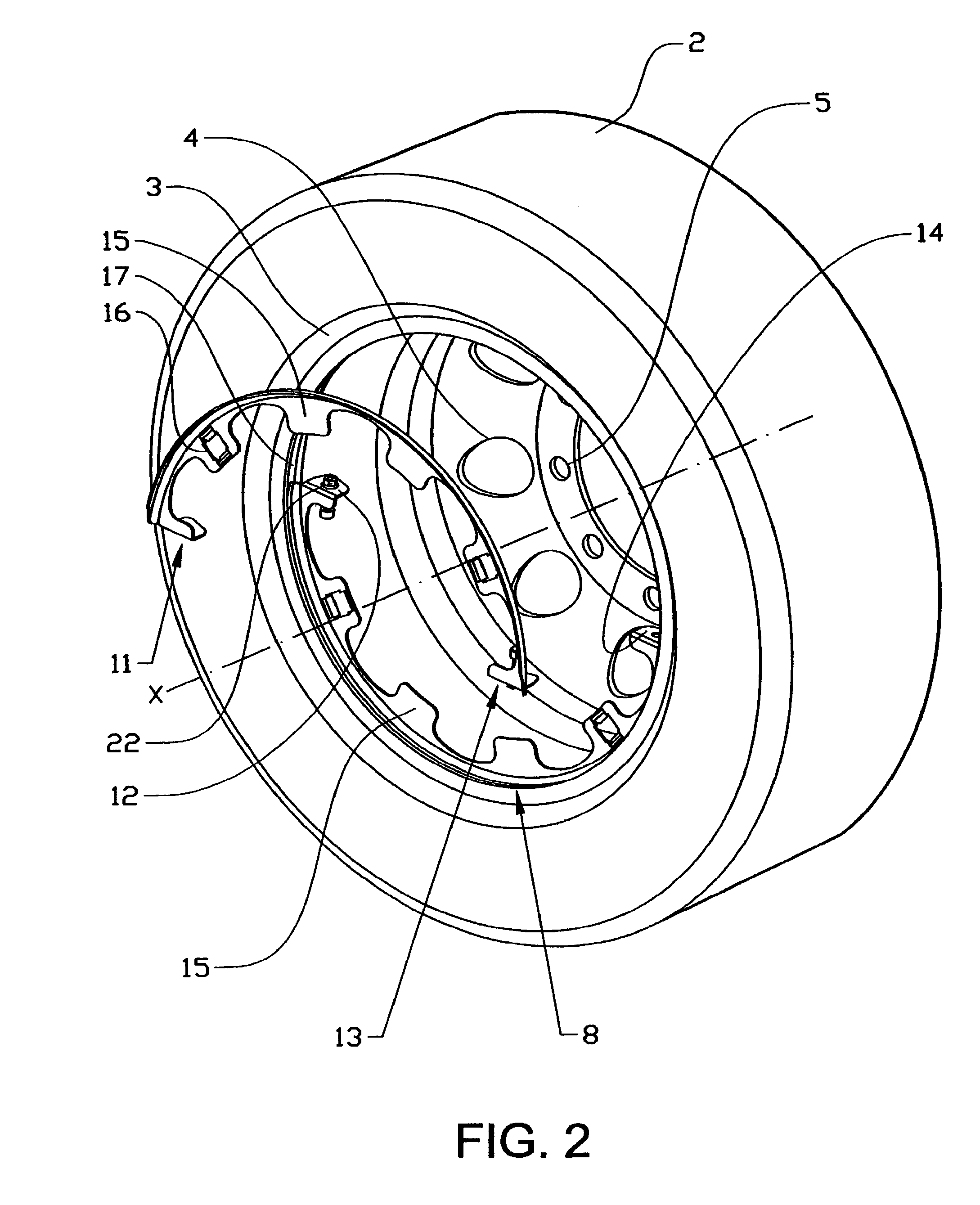
[0010]By pressing at least one pair of end surfaces apart in a tangential direction, a section or sections of the bracket will be expanded radially outwards until they come into contact with and are clamped securely against the inner periphery of the rim. Clamping is preferably undertaken against a slot or a radial edge on the inner periphery of the rim, for example at the so-called rim horn, said edge or slot preventing the bracket from being able to move in an axial direction relative to the rim after mounting. The contact surface of the bracket at its outer periphery preferably has a shape or a cross section matched to the contact surface of the rim. Fastening adjacent to the rim horn has the advantage that this surface is standardized on largely all types of rims. The bracket can thereby be provided with a fixed position that does not need to be subsequently adjusted.
[0012]A protective cover can also be mounted in that a number of fasteners on said protective cover interact with at least two openings in the bracket. According to this embodiment the protective cover may rest against a side of the second contact surface facing the hub. The openings, as stated above, may be arranged on an inner periphery of the second contact surface of the bracket or of through-holes in the second contact surface of the bracket. The same openings or holes can therefore be used for fastening different types of accessories. A protective cover of this type is preferably mounted in order to protect the wheel hub, wheel bolts or exposed parts of the brake caliper and the like from external influences.
[0016]A wheel cap or a protective cover is provided with a number of fasteners on its axially inner or outer side, the fasteners interacting with openings or holes in the second contact surface extending radially inwards in the bracket. In this case the fasteners of the wheel cap or protective cover interact with at least two openings in the second contact surface of the bracket, as described above. The fasteners suitably comprise snap couplings, such as clips or similar arrangements that permit rapid detachment of the wheel cap.

Problems solved by technology

A disadvantage with this design is that the wheel cap cannot be removed without tools, and that it only provides a limited protection against external influences.
Furthermore, it does not afford any protection against external influences.
The problems with these known fastenings are that the mounted accessories cannot be removed quickly, since they require tools for detachment, and that they are intended for rims having exposed fasteners on an axially outer part of the rim.

Method used


Image

  • Method, arrangement and bracket for mounting a rim accessory on a vehicle
  • Method, arrangement and bracket for mounting a rim accessory on a vehicle
  • Method, arrangement and bracket for mounting a rim accessory on a vehicle

Examples


Embodiment Construction

[0023]In the text below, unless otherwise stated the terms “inner” and “outer” relate to the location of various components in relation to a rim mounted on a vehicle axle, marked X. The terms “axial” and “radial” consequently relate to a location or extent in relation to the central axis of the rim, corresponding to the axle X.

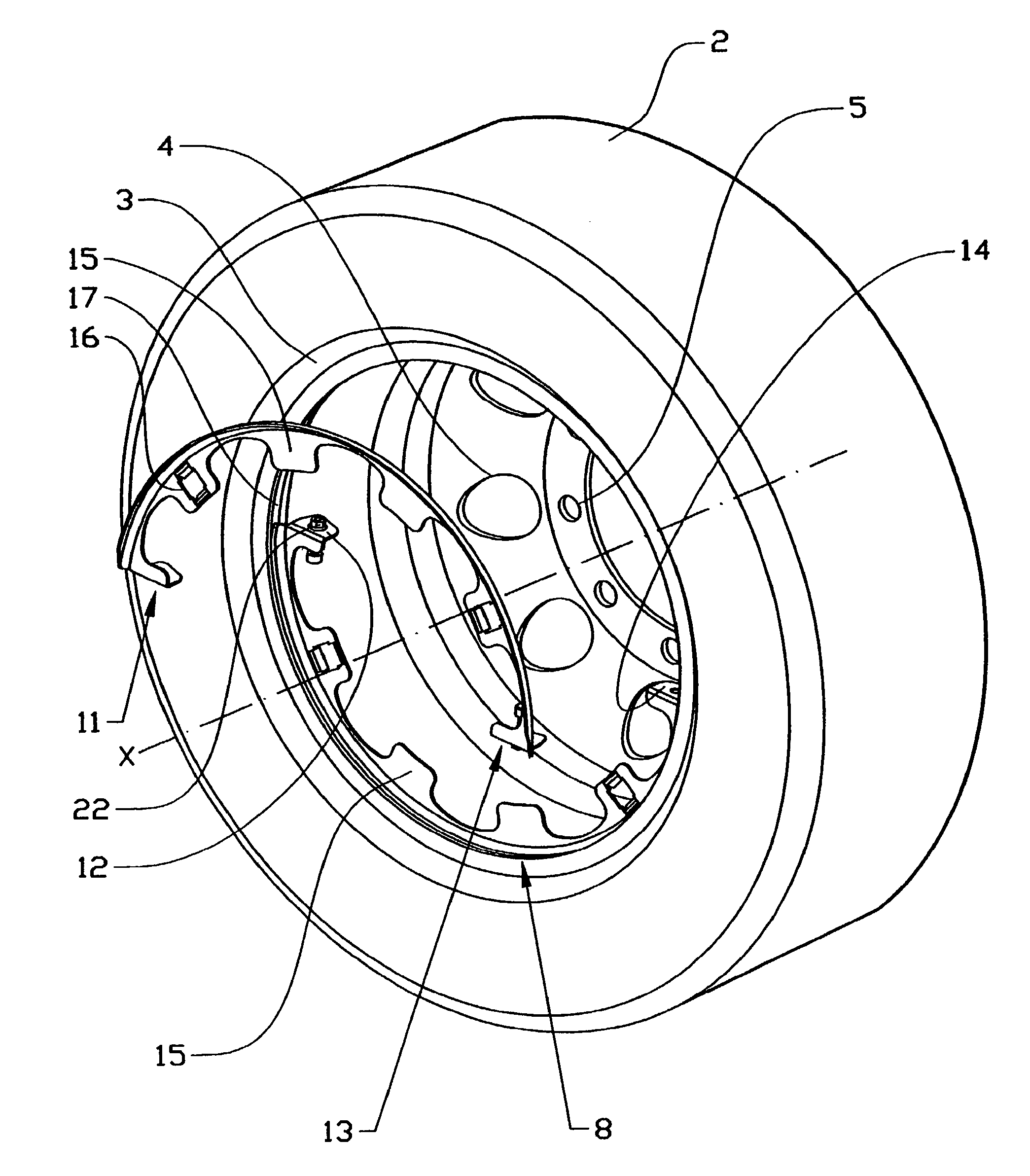
[0024]FIG. 1 shows a vehicle wheel having a bracket according to the invention, in this case a rear drive wheel for a heavy truck or a bus. The wheel 1 comprises a tire 2, mounted on a rim 3, the rim being provided with a number of openings 4 and a central section having a number of holes 5 for wheel bolts (not shown) for mounting the wheel 1 on a wheel hub (not shown) on the vehicle. When mounting the wheel 1, a bracket 6 with a peripherally outer contact surface is placed so that it rests against an interacting inner contact surface on the inner periphery of the rim (see FIG. 2). The bracket 6 comprises a pair of semicircular sections 7,8 connected by a pair...


PUM


Abstract

The invention relates to a method for mounting rim accessories on a vehicle, the vehicle having rims with fasteners for fastening the rim to a wheel hub, the method including mounting of a bracket including at least two sections, the bracket having a first contact surface along its outer periphery for resting against an interesting contact surface on the inner periphery of the rim, the radially inner contact surface lying substantially parallel to and adjoining an axially outer edge of the rim. The method includes mounting the bracket such that adjoining end surfaces of the sections of the brackets are forced apart, thereby clamping the bracket fast to the rim, and mounting of an accessory on the bracket, the bracket having at least a second contact surface extending radially inwards along the inner periphery of the rim. The second contact surface is provided with at least two openings in each of the sections of the bracket for interaction with at least a corresponding number of fasteners on the accessory. The invention also relates to an arrangement for mounting such an accessory and a bracket intended for this purpose.

Description

[0001]The present application is a continuation of International Application No. PCT / SE2004 / 001456, filed Oct. 12, 2004, which claims priority to SE 0302758-8, filed Oct. 17, 2003, both of which are incorporated by reference.BACKGROUND AND SUMMARY[0002]The invention relates to a method and an arrangement for quickly and easily mounting various rim accessories on a vehicle, the vehicle having rims with fasteners for fastening to a wheel hub on a drive wheel or on wheels intended for a trailer.[0003]There are nowadays many different ways of fastening wheel caps to rims for vehicles, such as trucks and buses, having exposed fasteners for fastening rims.[0004]U.S. Pat. No. 5,542,750, for example, shows a fastening in which a wheel cap is fastened directly or indirectly to a rim at least together with an annular disc having openings for the wheel nuts. The wheel cap is here screwed securely into said disc. A disadvantage with this design is that the wheel cap cannot be removed without to...

Claims


Application Information

Patent Timeline
Patent Type & Authority Patents(United States)
IPC IPC(8): B60B7/12B60B7/06B60B7/08
CPCB60B7/04B60B7/063B60B7/14B60B7/12B60B7/08
Inventor DAGH, INGEMARTRYGG, ANDERS
Owner VOLVO LASTVAGNAR AB
Learn More