
Heated cutting blade, cutting head, and blade mounting structure requiring less current and providing improved cutting and method

a technology of cutting blades and mounting structures, which is applied in the direction of manufacturing tools, portable power-driven tools, other domestic objects, etc., can solve the problems of power supply and transformer, significant heating is not provided where it is needed, and the resistance of blades heated by electricity passing through the resistance of blades has encountered substantial difficulties, so as to increase the electrical resistance and heating of the blade section, reduce the cross-sectional area of the blade, and fast and easy mounting resistance

Active Publication Date: 2011-10-27
VAN ALSTINE GUY A
View PDF8 Cites 2 Cited by
  • Summary
  • Abstract
  • Description
  • Claims
  • Application Information

AI Technical Summary

Benefits of technology

[0005]An advantage of the present invention is that it provides resistance heated cutting blades which require less current enabling the use of a smaller transformer and smaller power supply further enabling the entire cutting instrument to be incorporated into a handheld unit.
[0006]Another advantage of the present invention is that it provides a means of controlling where the heat will be supplied in the blade. This enables the heat to be controlled so that the heat is supplied to the portion of the blade which is in the heat sensitive material, such as rubber. Without the present invention, heat may be concentrated in portions of the blade which are outside of the heat sensitive material causing that portion of the blade to overheat.
[0007]Another advantage of the present invention is that it provides a means for quickly and easily mounting resistance heated electrical blades where the blades are aligned with the direction of cutting.
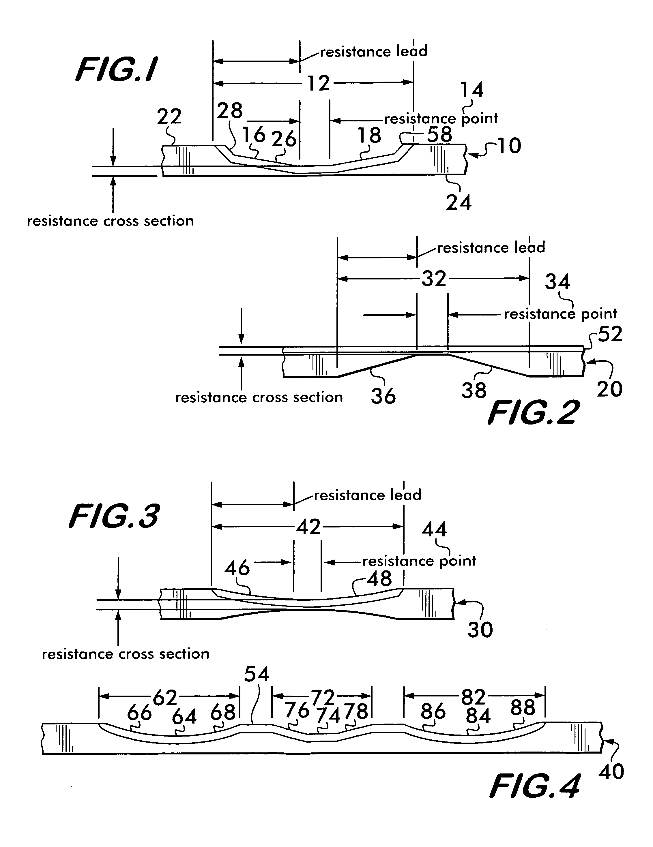
[0008]Briefly and basically in accordance with the present invention, a method of cutting a heat sensitive material using an electrically heated cutting blade includes the steps of shaping the blade to substantially reduce the cross-sectional area of the blade in a section of the blade between a first end and a second end of the blade to increase electrical resistance and heating of the blade section when an electrical current is passed through the blade thereby reducing the amount of current required to heat the section to a predetermined temperature. The blade may be reduced in cross-sectional area by more than 50% at a resistance point in the section. However, in certain situations, a reduction of thirty percent of the cross sectional area of the blade at the resistance point may be sufficient. The reduced cross sectional area may be achieved by reduction in width and or thickness of the blade. Also, the sharpening of the blade causes some reduction in the cross sectional area of the blade. The blade may be substantially U-shaped, L-shaped, in a single plane or any other suitable shape. The blade may have more than one section of reduced cross-sectional area. The sections of reduced cross-sectional area may be arranged to provide heating in desired sections of the blade and reduction of heating in other sections of the blade.
[0009]The present invention further comprises a blade for cutting heat sensitive material which comprises a conductive or steel blade having a first and second end and the blade between the first and second ends having a section of reduced cross-sectional area producing increased electrical resistance and heating when an electrical current is passed therethrough. Steel is defined herein to mean any metal which contains iron and carbon including but not limited to stainless steel and may include various other metals such as vanadium, chromium, nickel or various other metals or alloys thereof. The reduced cross-sectional area of the blade is provided with a sharpened edge. The section of reduced cross-sectional area is at least at one point reduced in cross-section by greater than 50% compared to the cross-sectional area of the remainder of the unshaped blade. The section of reduced cross-sectional area producing increased resistance may be provided with a resistance lead on each side in the form of a taper of the blade. The taper may be linear, non-linear, multiple non-linear sub sections or multiple linear sub sections of differing rates of linear taper. It is understood that non linear taper and differing rates of taper include the case where the taper occurs in the distance approaching zero and is effectively discontinuous or effectively changes from full cross sectional area to maximum reduced cross sectional area in substantially zero distance. The blade may be provided with a plurality of sections of reduced cross-sectional area in series in the blade. The section of reduced cross-sectional area may be centrally located between the first and the second ends of the blade or may be located closer to one end. The blade may be substantially U-shaped, L-shaped or substantially within a single plane (flat).
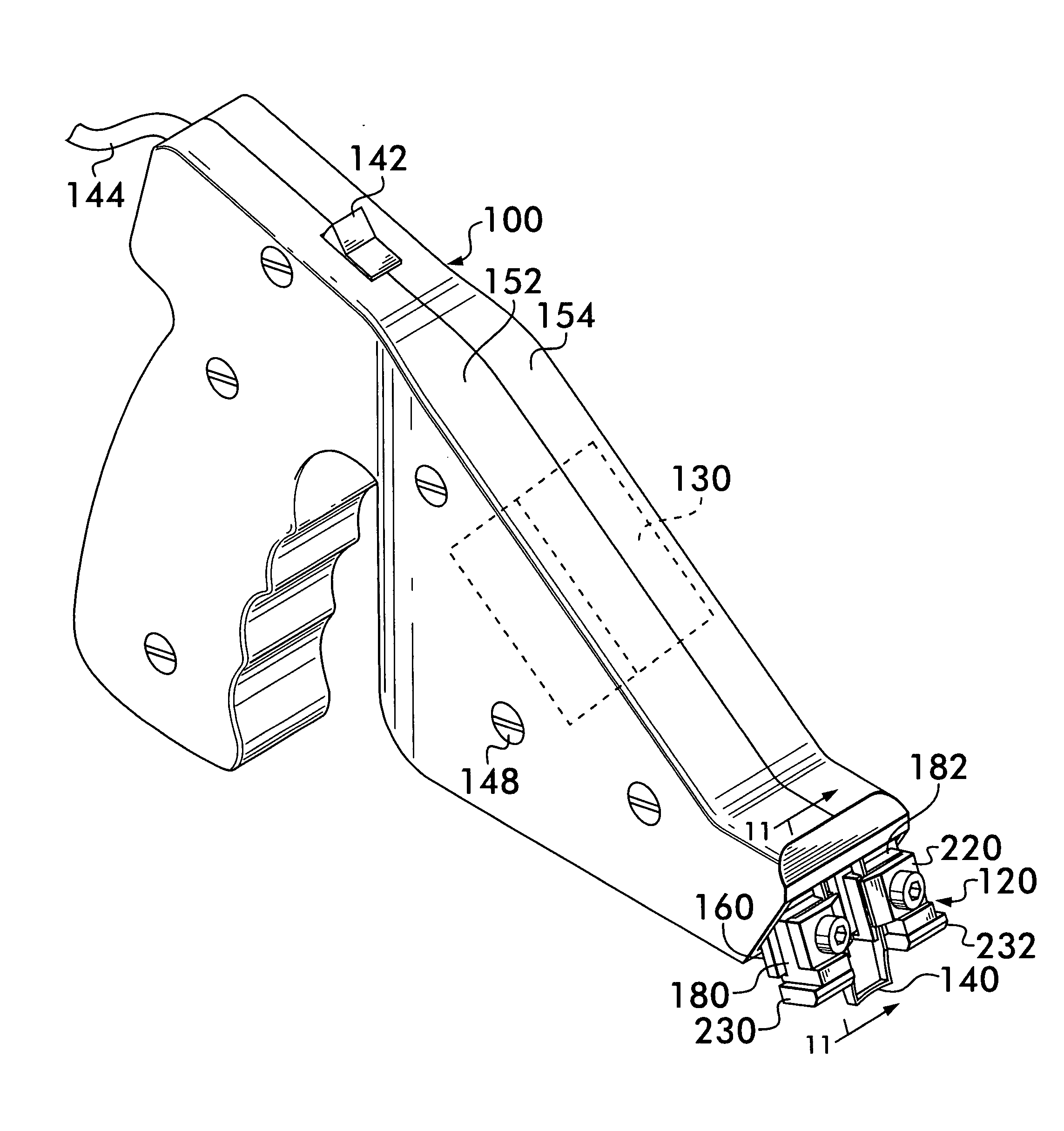
[0010]Further, briefly and basically in accordance with the present invention an apparatus is provided for making a groove in a heat sensitive material which comprises a substantially U-shaped blade, a handheld unit for holding the substantially U-shaped blade with the substantially U-shaped blade having at least one section of reduced cross-sectional area to increase its electrical resistance, and a power supply for providing electrical current to the substantially U-shaped blade with the power supply being mounted in the handheld unit.

Problems solved by technology

In the field of tire grooving and regrooving as well as the cutting of other heat sensitive material such as rubber or plastic belts or bands and the like, blades heated by electricity passing through the resistance of the blade have encountered substantial difficulty with blades heating in areas where the blade is not in the heat sensitive material and accordingly overheating.
Further, significant heating is not provided where it is needed.
Further, in this field since there is a substantial amount of electricity required for the electrical resistance heating, the power supply and transformer are large and heavy requiring a separate power supply unit which is then connected to the cutting head by large heavy cables.
This proved to be cumbersome in moving large heavy cables around as well as being tied to the power supply which must necessarily be located nearby.
Wenger does not disclose shaping of a blade to produce an electrical resistance which reduces the current requirements enabling the entire unit including the power supply to be incorporated into the hand held unit.
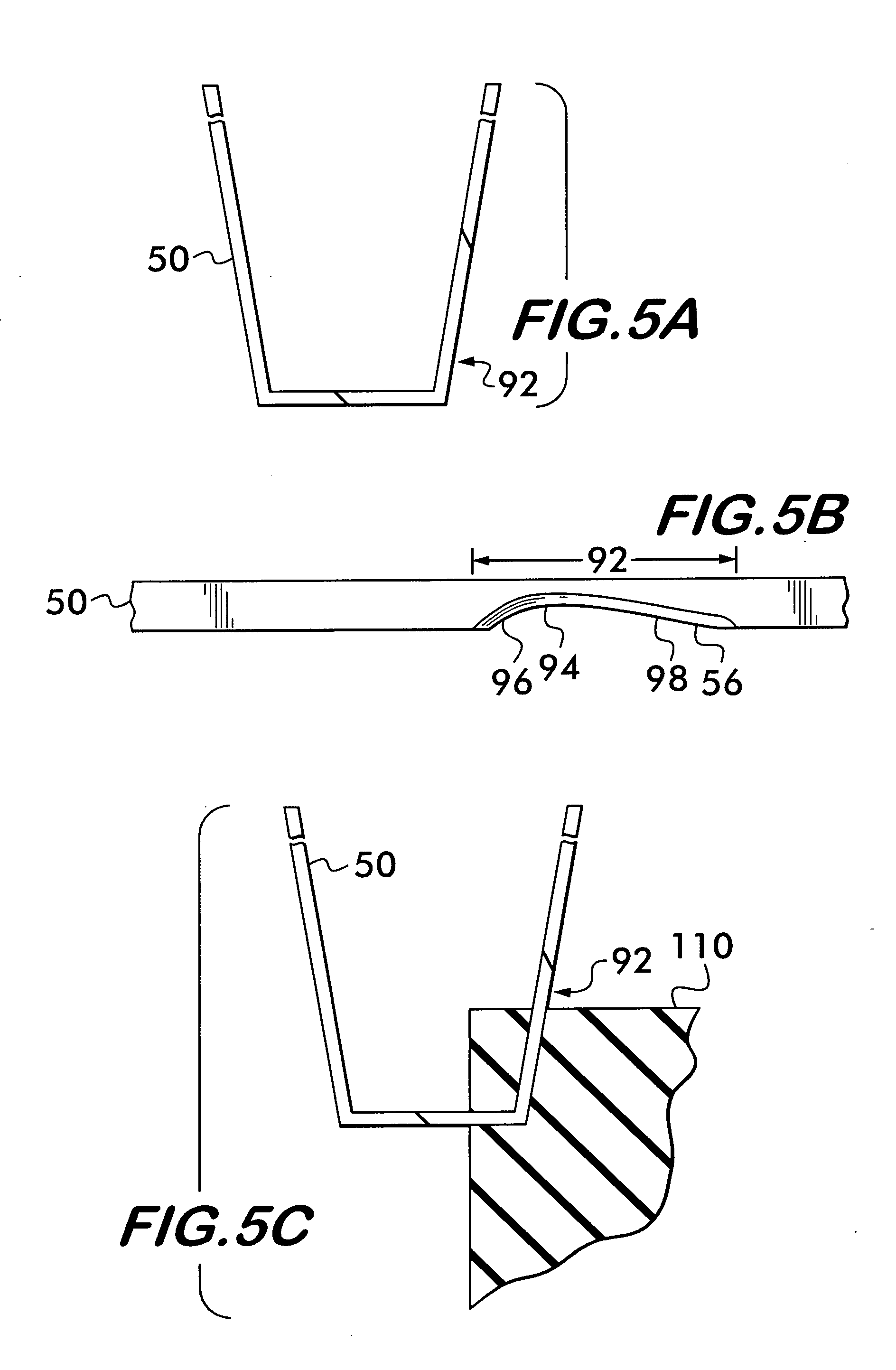
Further, in the prior art the installation or changing of the blade proved to be a cumbersome process and the clamping of the blades to the cutting instrument often distorted the blades such that the blade legs were not aligned with the direction of cutting.
For example, see U.S. Pat. No. 2,896,059—Ruff which discloses a mounting head assembly for an electrically heated cutting tool wherein the blades are mounted in grooves in a movable supporting block which rotates somewhat upon tightening of screws resulting in twisting the blade arms resulting in the blade arms not being aligned with the direction of cutting.
Further, since the blade arms need to be inserted into the grooves and the grooves are movable because they are formed in a movable supporting block, the mounting of new blades is made difficult.
As is common in the prior art, the fact that the movable supporting block of Ruff is not held away from the face of the cutting head, further makes it difficult to insert the blades.
Still further, the mounting head assembly of Ruff, as is common in the prior art, requires that the ends of the blade mate with the ends of the slots, which is much like threading a needle, and particularly difficult since the slots are moving.

Method used


Image

  • Heated cutting blade, cutting head, and blade mounting structure requiring less current and providing improved cutting and method
  • Heated cutting blade, cutting head, and blade mounting structure requiring less current and providing improved cutting and method
  • Heated cutting blade, cutting head, and blade mounting structure requiring less current and providing improved cutting and method

Examples


Embodiment Construction

[0045]Referring now to the drawings, wherein like numerals indicate like elements, there is shown in FIG. 1 a blade 10 in accordance with the present invention for cutting heat sensitive materials, such as rubber, plastic or other heat sensitive materials, which requires a smaller current to heat the resistance point to a predetermined temperature suitable for cutting the heat sensitive material. Blade 10 is shaped to substantially reduce the cross sectional area of the blade in a section 12 extending as illustrated in FIG. 1 and including resistance point 14 and resistance lead taper sections 16 and 18. Section 12 has a substantially reduced cross sectional area as compared to the end portions of the blade, such as first end 22 and second end 24. “End or end portion of the blade” does not necessarily mean the very end of the blade, but portions of the blade where the cross sectional area is not reduced, not sharpened and is used for attachment to the mounting structure of a cutting...


PUM

PropertyMeasurementUnit
currentaaaaaaaaaa
areaaaaaaaaaaa
voltageaaaaaaaaaa

Abstract

The present invention provides a method and apparatus of reducing current requirements by increasing resistance of the blade structure by reducing the cross sectional area of at least one section of the blade so that the electrical current requirements for heating of the blade to cutting temperature are reduced wherein the power supply and substantially entire unit may be mounted within a hand held unit. Methods of shaping blades to perform various heat distributions for specialty blades for custom cutting are disclosed. Further, an improved blade mounting structure is provided which includes structure for maintaining the legs of the blade parallel to the direction of cut and provides for easy insertion of new blades by maintaining a slotted blade cradle stable and in alignment with the blades and a clamp member away from the blade when the clamp mounting structure is loosened.

Description

FIELD OF THE INVENTION[0001]The present invention relates to field of cutting heat sensitive material using a blade which is heated by the passage of current through the resistance of the blade. Particularly, a new and improved resistance heated cutting blade, cutting head and blade mounting structure which require less current and provide improved cutting are disclosed along with the method of producing these effects. More particularly, in accordance with the present invention a blade for cutting a heat sensitive material which is heated by the passage of current through the resistance of the blade is provided with selected sections of reduced cross sectional area to reduce the amount of current flow required through the blade to achieve a predetermined amount of heating and to control the area or areas of heating of the blade. The reduction in the amount of current flow required by the blade enables the use of a smaller and lighter transformer and power supply which enables the en...

Claims


Application Information

Patent Timeline
Patent Type & Authority Applications(United States)
IPC IPC(8): B26D7/10B26D3/00
CPCB26B5/00B26D1/0006B26D3/003B26D2001/0053B26D7/10B26D7/2614B26D3/06B23D35/008B26F3/08B29D29/06B29D30/68Y10S83/951Y10T83/0304Y10T83/04Y10T83/293Y10T83/9457Y10T83/9461Y10T83/9488Y10T83/949
Inventor VAN ALSTINE, GUY A.
Owner VAN ALSTINE GUY A
Learn More