
Arrangement and method for mounting a wheel cap on a vehicle

a technology for mounting and wheel caps, which is applied in the direction of wheel protection, vehicle components, transportation and packaging, etc., can solve the problems of not being able to remove the wheel caps without tools, providing limited protection against external influences, and not affording any protection against external influences. , to achieve the effect of less susceptible to damage and quick detachment of the wheel caps

Inactive Publication Date: 2006-07-20
VOLVO LASTVAGNAR AB
View PDF13 Cites 5 Cited by
  • Summary
  • Abstract
  • Description
  • Claims
  • Application Information

AI Technical Summary

Benefits of technology

[0002] The invention relates to a method and an arrangement for quickly and easily mounting a wheel cap on a vehicle, the vehicle having rims with exposed fasteners for fastening the rim to a wheel hub.
[0007] It is desirable to provide an arrangement for quick and easy mounting of a wheel cap on a vehicle.
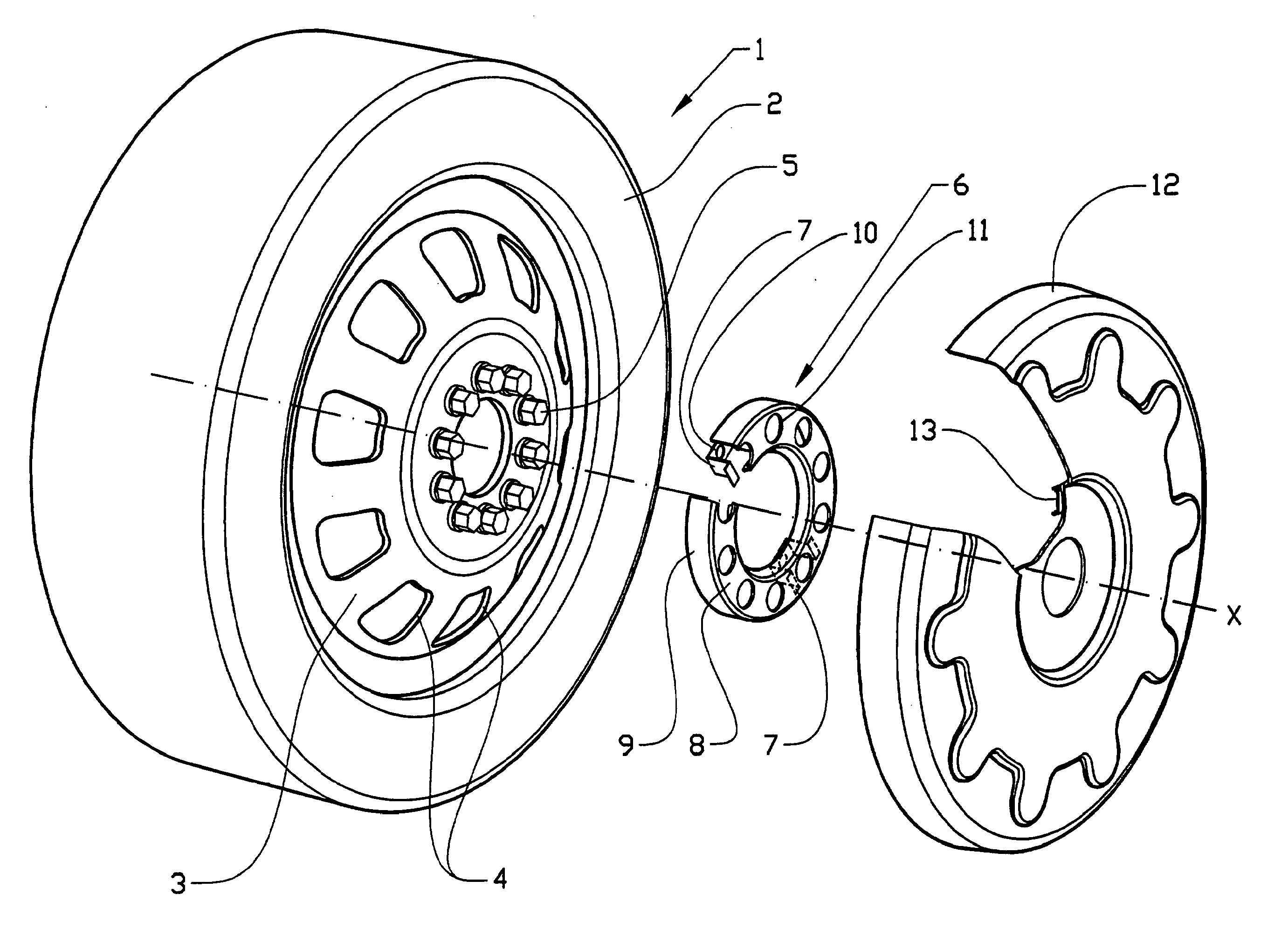
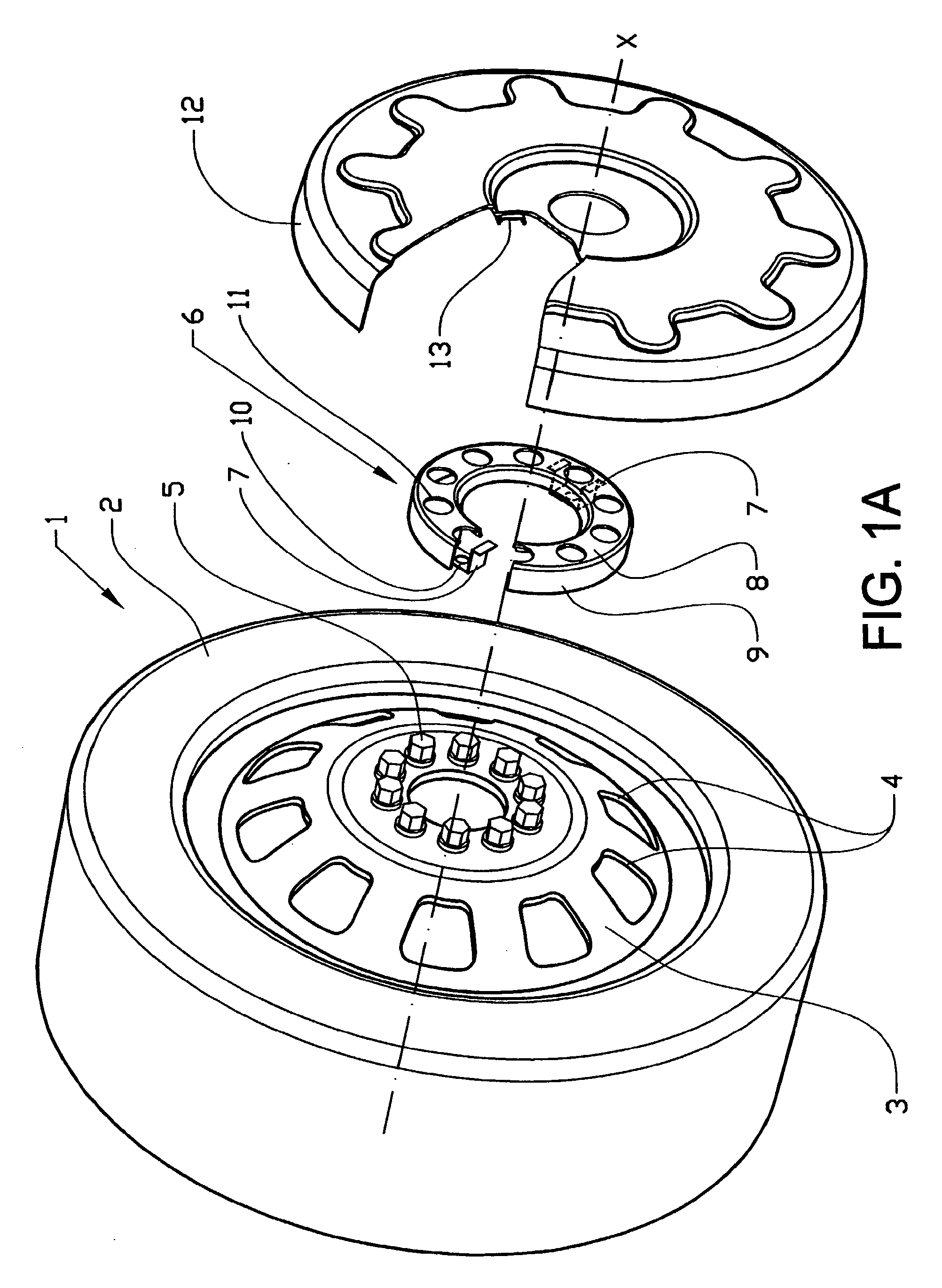
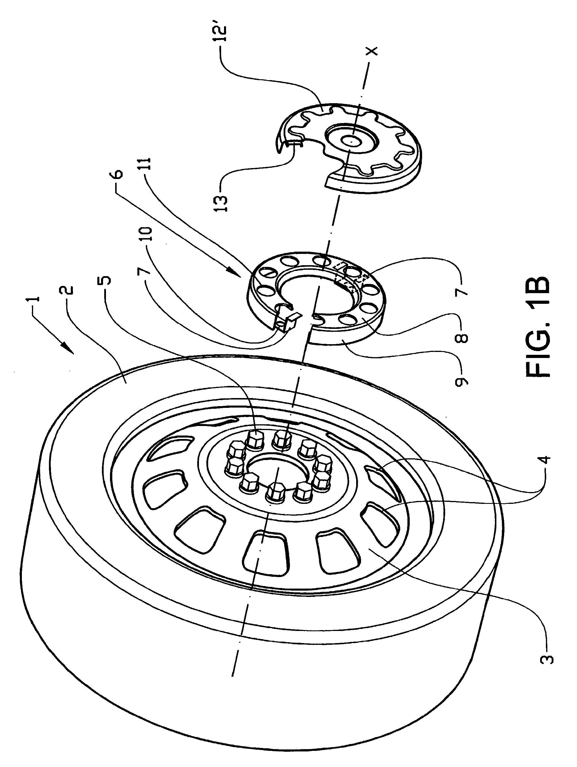
[0012] The holder may be formed with a first, inner surface and a second, outer surface, the surfaces having either the same shape or different shapes. The first surface may comprise, for example, a number of separate attachments, the contact surfaces of which against the rim constitute the first surface. Here the second surface may be circular or annular, with suitable inside and outside diameters. Alternatively, the first and second surface may have the same inside and outside diameter respectively and be joined to one another along the periphery of an inner or an outer edge of the respective surface. The holder is located against the outer side of the rim and at least the first, inner surface is therefore parallel to the rim. The second, outer surface is preferably parallel to the first surface but may be somewhat convexly or concavely conical. However, both the first and the second surface are arranged concentrically with the axis of rotation of the wheel. The distance between the first and the second surface is somewhat greater than the extent to which the wheel bolts or the wheel nuts protrude axially from the outer surface of the rim. The holder can thereby both protect persons and objects in the surroundings from the otherwise protruding wheel bolts, and protect the wheel bolts or nuts against damage caused by external influences. The outer part of the holder must also be designed to withstand forces acting parallel to the second surface, for example if the driver should use the holder as a step when the vehicle is parked in tight spaces.
[0014] The wheel cap may be provided with a number of fasteners, which are preferably detachably secured in openings in the second surface of the holder. The fasteners interact with at least two openings in the second surface of the holder, the openings corresponding to the number of rim fasteners as specified above. Alternatively, the wheel cap may be fastened to a radially inner or outer edge of the second surface of the holder. The wheel cap fasteners suitably comprise snap couplings, such as clips or similar arrangements that permit rapid detachment of the wheel cap. An advantage with clips is that the fastening is less susceptible to damage and out-of- roundness of the outer surface. The fasteners may naturally also be fastened to the second surface of the holder for detachable fastening in openings in the inner surface of the wheel cap. The diameter of the wheel cap may be selected between a minimum diameter largely corresponding to the diameter of the second surface of the holder and a maximum diameter largely corresponding to the axially outer diameter of the rim.

Problems solved by technology

A disadvantage with this design is that the wheel cap cannot be removed without tools, and that it only provides a limited protection against external influences.
Furthermore, it does not afford any protection against external influences.
The problems with these known fastenings are therefore that they cannot be removed quickly, since they require tools for detachment, and that they afford scant protection, if any, either for the surroundings or for wheel bolts or wheel nuts.

Method used


Image

  • Arrangement and method for mounting a wheel cap on a vehicle
  • Arrangement and method for mounting a wheel cap on a vehicle
  • Arrangement and method for mounting a wheel cap on a vehicle

Examples


Embodiment Construction

[0023] In the text below, unless otherwise stated, the terms “inner” and “outer” relate to the location of various components in relation to a rim mounted on a vehicle axle, marked X. The terms “axial” and “radial” consequently relate to a location or extent in relation to the central axis of the rim.

[0024]FIG. 1A shows a vehicle wheel according to the invention, in this case a front wheel for a heavy truck or a bus. The wheel 1 comprises a tire 2, mounted on a rim 3, the rim being provided with a number of openings 4 and a central section having a number of holes (not shown) for wheel bolts 5 for mounting the wheel 1 on a wheel hub (not shown) with an axis of rotation X on the vehicle. When mounting the wheel 1, a holder 6 is placed against the rim 3 and is securely bolted by means of the wheel bolts 5. The holder 6 comprises attachments 7 having a pair of first contact surfaces 7′, for resting against the rim 3, and a second contact surface 8, for resting against the wheel cap an...


PUM


Abstract

The invention relates to a method and an arrangement for mounting a wheel cap on a vehicle, the vehicle having rims with exposed fasteners for fastening to a wheel hub. The method includes mounting of a holder by fasteners of the rim, the holder having a first contact surface for resting against the rim and a second contact surface lying substantially parallel to and at a distance from the first contact surface, and where the mounting of the holder is done by means of at least two fasteners of the rims interacting with openings in the first contact surface of the holder. The method includes mounting of the wheel cap on the holder by a plurality of fasteners on the inner side of the wheel cap interacting with openings for the fasteners of the rim in the second contact surface of the holder.

Description

BACKGROUND AND SUMMARY [0001] The present application is a continuation of International Application No. PCT / SE2004 / 001455, filed Oct. 12, 2004, which claims priority to SE 0302757-0, filed Oct. 17, 2003, both of which are incorporated by reference. [0002] The invention relates to a method and an arrangement for quickly and easily mounting a wheel cap on a vehicle, the vehicle having rims with exposed fasteners for fastening the rim to a wheel hub. [0003] There are nowadays many different ways of fastening wheel caps to rims for vehicles, such as trucks and buses, having exposed fasteners for fastening rims. [0004] U.S. Pat. No. 5,542,750, for example, shows a fastening in which a wheel cap is fastened directly or indirectly to a rim at least together with an annular disc having openings for the wheel nuts. The wheel cap is here screwed securely into the disc. A disadvantage with this design is that the wheel cap cannot be removed without tools, and that it only provides a limited p...

Claims


Application Information

Patent Timeline
IPC IPC(8): B60B7/14B60B7/06
CPCB60B7/04B60B7/068B60B7/10B60B7/14
Inventor DAGH, INGEMARTRYGG, ANDERS
Owner VOLVO LASTVAGNAR AB
Learn More