Eureka AIR delivers breakthrough ideas for toughest innovation challenges, trusted by R&D personnel around the world.

Connector assembly

Inactive Publication Date: 2009-10-13
ALL BEST ELECTRONICS
View PDF9 Cites 40 Cited by
  • Summary
  • Abstract
  • Description
  • Claims
  • Application Information

AI Technical Summary

Benefits of technology

[0004]A primary object of the present invention is to overcome the problems in the conventional connectors by providing a connector assembly suitable for use with connector chip modules that will produce a high amount of heat during operation thereof, so that the connector assembly can be widely applied to all kinds of connector chips.

Problems solved by technology

However, new problems arise with the miniaturized and integrated electronic elements to result in reduced element reliability.
However, it is impossible to achieve the 100% efficiency, and some power is wasted and converted into heat energy, which would cause largely risen operating temperature of the whole system.
In the event the operating temperature exceeds an allowable limit, errors might occur in the system operation.
In worse conditions, the system might become failed or burned out due to overheat.
As a result, the new-generation electronic products produce more heat when they operate, and are therefore more easily subject to high operating temperature that exceeds the allowable limit to form another problem.

Method used


Image

  • Connector assembly
  • Connector assembly
  • Connector assembly

Examples


first embodiment

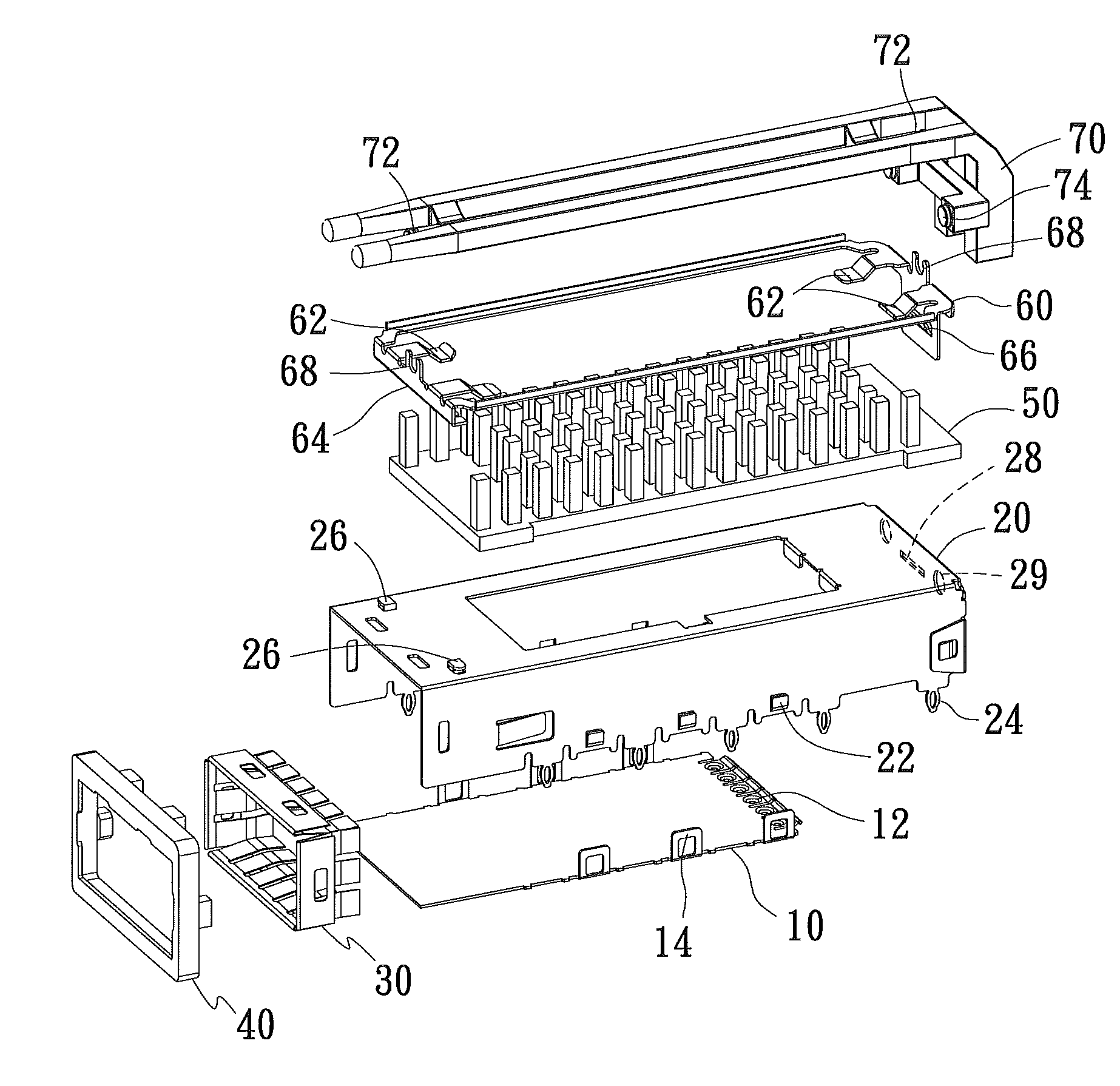
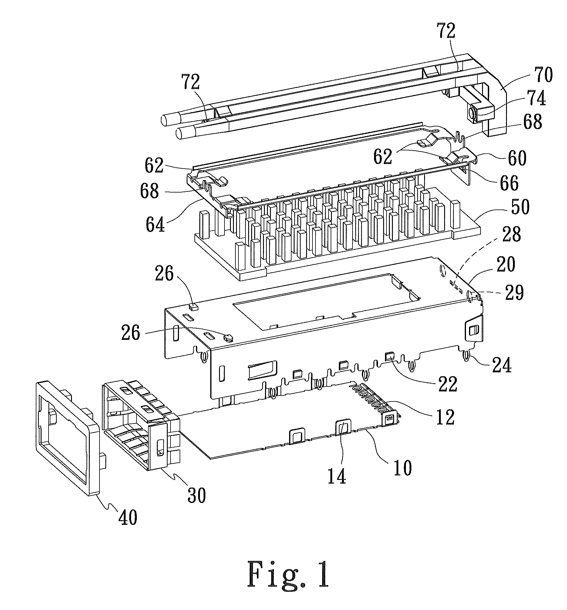
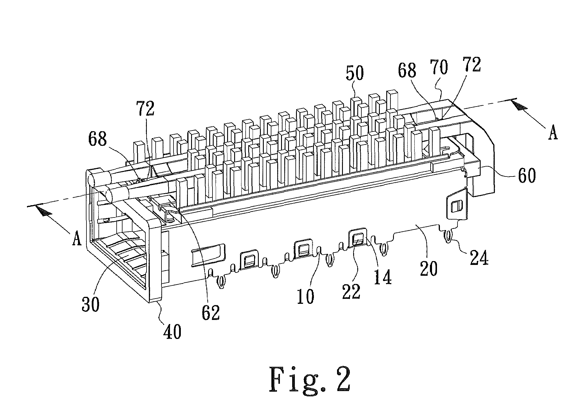
[0018]In the connector assembly according to the present invention, the heat-sink fastening member 60 can be further provided at the front and rear ends with an open-topped recess 68 each. Meanwhile, the light guiding member 70 is further provided with two round posts 72 corresponding to the two recesses 68, so that the light guiding member 70 is disposed on the top of the heat-sink fastening member 60 with the two round posts 72 engaged with the two recesses 68.

[0019]In the connector assembly according to the first embodiment of the present invention, the upper cover 20 can be further provided on the rear end wall with a pair of spaced second through holes 29. Meanwhile, the light guiding member 70 is further provided at positions corresponding to the pair of second through holes 29 with two forward projected bosses 74 for extending through and thereby engaging with the pair of second through holes 29.

[0020]The engaged recesses 68 and round posts 72 ensure firm and stable connectio...

second embodiment

[0026]In the connector assembly according to the present invention, each of the heat-sink fastening members 60′ can be further provided at the front and rear ends with an open-topped recess 68′ each. Meanwhile, each of the light guiding members 70′ is further provided with two round posts 72′ corresponding to the two recesses 68′, so that each of the light guiding members 70′ is disposed on the top of one of the heat-sink fastening members 60′ with the two round posts 72′ engaged with the two recesses 68′.

[0027]In the connector assembly according to the second embodiment of the present invention, the upper cover 20′ can be further provided on the rear end wall with a plurality of pairs of spaced second through holes 29′. Meanwhile, the light guiding members 70′ each are further provided at positions corresponding to one pair of the second through holes 29′ with two forward projected bosses 74′ for extending through and thereby engaging with the pair of second through holes 29′.

[0028...


PUM


Abstract

A connector assembly is suitable for use with various types of connector chip modules, and includes a heat sink detachably connected to a top of a cover of the connector assembly via a heat-sink fastening member, so that heat produced by the connector chip module on the connector assembly during the operation thereof can be effectively dissipated into ambient environment via the heat sink. Therefore, the connector assembly can be widely applied to all kinds of connector chips.

Description

FIELD OF THE INVENTION[0001]The present invention relates to a connector assembly, and more particularly to a connector assembly provided with a heat sink to enable effective dissipation of heat produced by a connector chip module inserted in the connector assembly.BACKGROUND OF THE INVENTION[0002]With the coming of the globalization age, people require work efficiency and convenience much higher than ever before. Consumers of nowadays prefer to purchase electronic products that can achieve more functions within the shortest possible time or at the highest possible efficiency. Therefore, to satisfy the consumers' requirements, it is a must to break through the bottleneck in the electronic industrial fields by researching and developing a new generation of products that are compact in volume, provide multiple functions, and work at high efficiency. When viewing from the point of research and development, techniques for the semiconductor process and integrated circuit (IC) design have...

Claims


Application Information

Patent Timeline
IPC IPC(8): H01R13/02
CPCG02B6/0008H01R13/7172H01R13/65802G02B6/4201G02B6/4292G02B6/4261G02B6/4269H01R13/6583
Inventor YANG, HAVEN
Owner ALL BEST ELECTRONICS
Why Eureka
Eureka Blog
Learn More