Reverse osmosis filtration systems

a filtration system and reverse osmosis technology, applied in the direction of membranes, separation processes, multi-stage water/sewage treatment, etc., can solve the problems of unfavorable water dispensing, and unfavorable water dispensing of initial products, etc., to achieve the effect of reducing the number of units

Active Publication Date: 2009-10-13
TOPPER MFG CORP
View PDF92 Cites 50 Cited by
  • Summary
  • Abstract
  • Description
  • Claims
  • Application Information

AI Technical Summary

Problems solved by technology

However, because the bladder is flat against the tank wall, it takes a moment for the squeeze water to seep between the bladder and the tank wall.
Therefore there is an initial hesitation in squeeze water flow, and accordingly in product water pressurization, providing an undesired hesitation and uncertainty in the initial product water dispensing.
While these components can be coupled together with conventional hose fittings and the like, such an arrangement tends to be a bit kludgy and labor intensive to assemble and service, and tend to be larger than necessary.

Method used


Image

  • Reverse osmosis filtration systems
  • Reverse osmosis filtration systems
  • Reverse osmosis filtration systems

Examples


Embodiment Construction

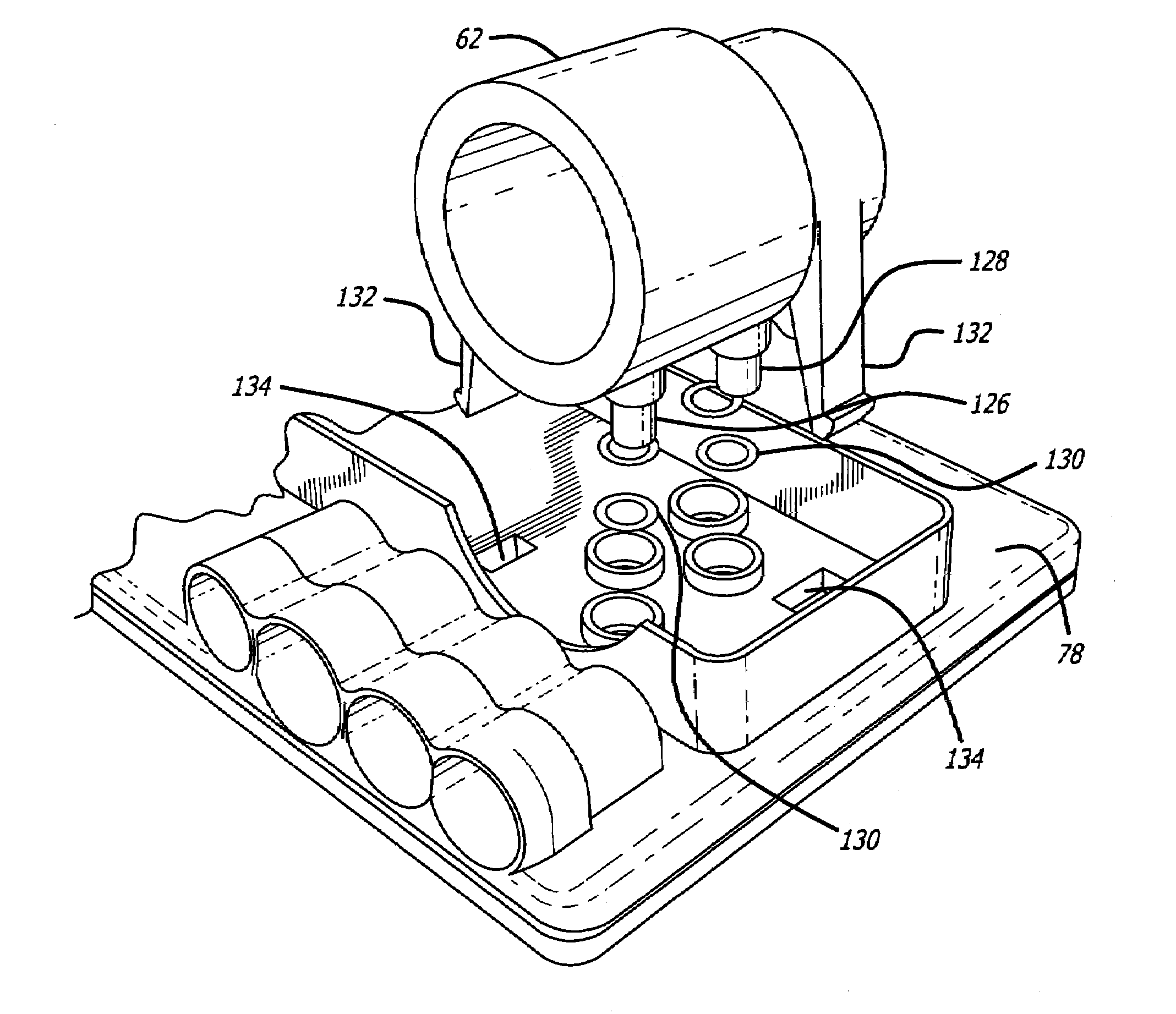
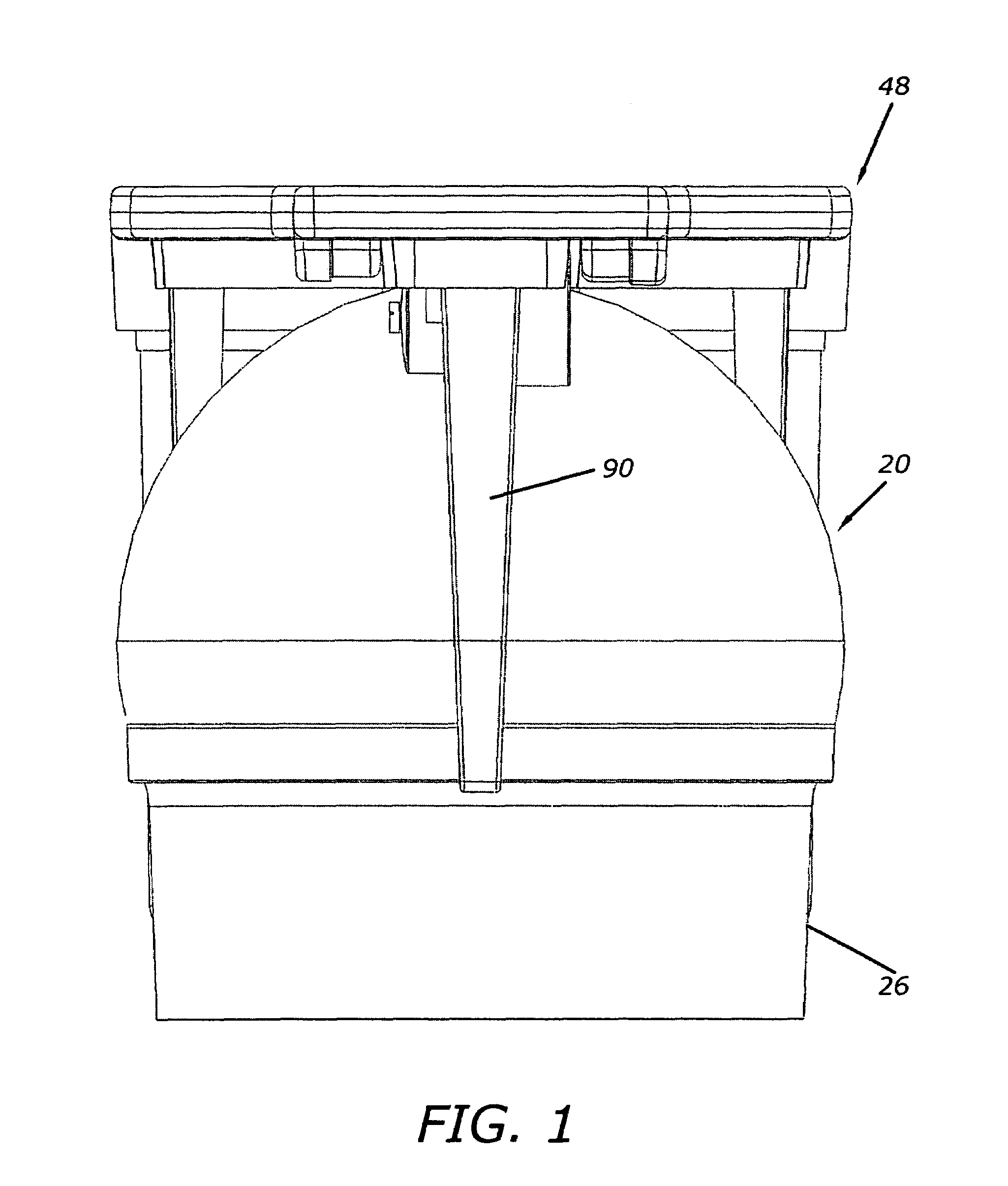
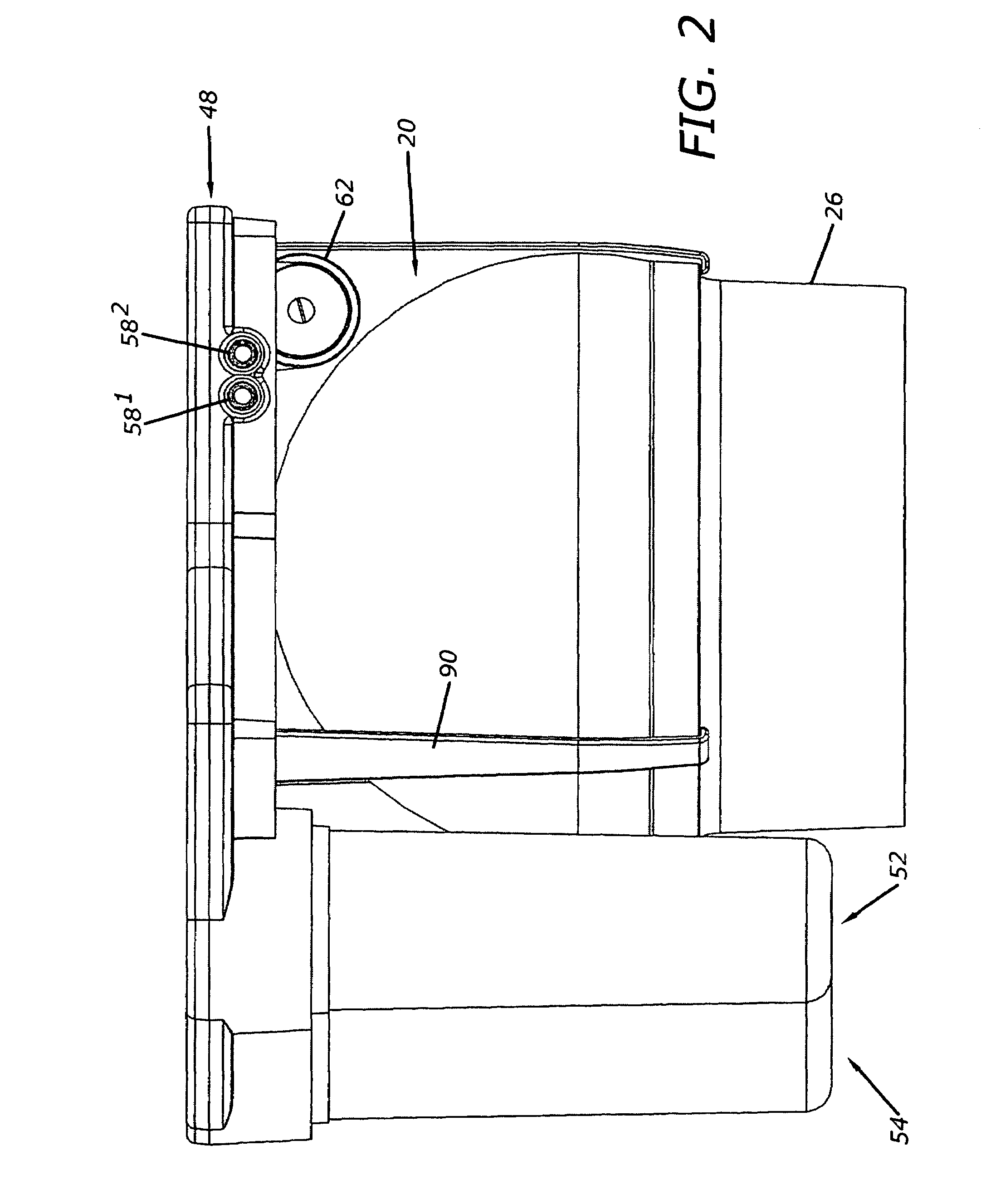
[0022]The present invention comprises integrated reverse osmosis filtration systems of a compact design having a minimum number of parts and easily connected and serviced, and suitable for use above or below a counter. An embodiment of the present invention may be seen in FIGS. 1 through 4. FIG. 1 is a first end view of one embodiment reverse osmosis filtration system of the present invention, FIG. 2 is a first side view, FIG. 3 is a second side view, and FIG. 4 is a bottom view. In FIG. 1, the main components that are visible are the storage tank for the storage of product water, generally indicated by the numeral 20, and a top plate assembly, generally indicated by the numeral 48. As shall subsequently be seen, the top plate assembly is a manifold assembly providing all water interconnections required within the system. In FIGS. 2 and 3, also visible are cartridges 52, 54 and 56 that contain a conventional filter, a reverse osmosis filtration membrane and an activated charcoal fil...


PUM

PropertyMeasurementUnit
areaaaaaaaaaaa
flexibleaaaaaaaaaa
thicknessaaaaaaaaaa

Abstract

Reverse osmosis filtration systems that are self contained and easily converted from above the counter use to below the counter use. The systems feature a simple construction, including a two piece manifold assembly to which filters, including a reverse osmosis filter, a product water storage tank and a control valve connect, all without separate fasteners. The manifold assembly provides all water connections within the system, and includes connections to connect to a water supply, a drain, two dispensers and to an auxiliary water storage tank. The system pressurizes squeeze water for product water dispensing, providing maximum efficiency, maximum storage capacity for a given tank size and maximum pressure for dispensing product water. Various embodiments are disclosed.

Description

CROSS-REFERENCE TO RELATED APPLICATION[0001]This application claims the benefit of U.S. Provisional Patent Application No. 60 / 711,837 filed Aug. 26, 2005.BACKGROUND OF THE INVENTION[0002]1. Field of the Invention[0003]The present invention relates to the field of reverse osmosis filtration systems.[0004]2. Prior Art[0005]Reverse osmosis water filtration systems pressurize one side of an appropriate membrane with source water, causing the water to slowly pass through the membrane, leaving impurities therein on the source water side of the membrane for flushing away by controlled flow of excess source water past the membrane. The filtered or product water passing through the membrane is accumulated in a storage tank having a flexible bladder separating the storage tank into a product water storage area and a squeeze water area. Normally when the product water storage tank area defined by the bladder is filled, the bladder lies flat against the tank wall. Now when the product water is ...

Claims


Application Information

Patent Timeline
Patent Type & Authority Patents(United States)
IPC IPC(8): B01D63/00B01D61/00
CPCB01D61/025B01D61/12C02F1/441C02F9/005B01D61/08B01D2313/125B01D2201/165B01D2201/4015B01D2201/4084B01D2311/2626B01D2311/2649B01D2313/02B01D2313/04B01D2313/13B01D2313/18B01D2313/20B01D2313/21B01D2313/246B01D2313/44B01D2313/50C02F1/001C02F1/283C02F2201/004C02F2201/005C02F2201/006C02F2201/007C02F2307/10B01D2313/105Y10T137/0402C02F9/20C02F1/44
Inventor BEALL, TIMOTHY A.
Owner TOPPER MFG CORP
Why Eureka
Try Eureka