Spring energized debris barrier for mechanically set retrievable packer

a debris barrier and mechanical setting technology, applied in the direction of sealing/packing, fluid removal, borehole/well accessories, etc., can solve the problems of not being able to achieve optimal grip, not having 360 protection, and being prone to rip

Active Publication Date: 2009-10-20
BAKER HUGHES INC
View PDF8 Cites 16 Cited by
  • Summary
  • Abstract
  • Description
  • Claims
  • Application Information

AI Technical Summary

Benefits of technology

[0007]A debris barrier for a retrievable mechanical set packer is held retracted for run in. It is held spaced apart from upper slips and uses a spring bias that acts on the slips to keep them energized to also energize the barrier to the extended position to keep debris out of the upper slips when the packer is set. The debris barrier is preferably a sleeve that is axially compressed by the setting procedure to increase in diameter and span the gap between the packer mandrel and the set upper slips. Retrieving the packer is enabled by a retraction of the debris barrier as the upper slips are undermined with rotation and pickup force on the packer mandrel. The lack of a debris barrier could prevent retrieval of the packer in well bores where debris is present and has a tendency to settle around and more critically under the upper slips.

Problems solved by technology

While the design appears to address the problem on paper, it has many practical limitations.
Directly forcing a ring to enlarge in diameter and move up an inclined ramp several issues are encountered.
If this happens it will move up the ramp unevenly leaving less than 360 protection and is also likely to rip before becoming wedged against the surrounding tubular.
Another concern from this type of wedging action is that the debris barrier can be subjected to a wedging force that can be sufficient to extrude it, which can also result in a tear.
If the ring is dependent of slip movement to ramp it out, any failure along the ramp can result in pieces of the ring acting as a brake on movement of the slip assembly up the ramp.
As a result, a less than optimal grip is obtained and the set packer is exposed to the possibility of loss of grip.
While debris barriers have been offered in pressure set packers that rely on driving a setting piston to actuate the slips and sealing element, such barriers have not been available on mechanical set packers that are also designed to be retrievable.

Method used


Image

  • Spring energized debris barrier for mechanically set retrievable packer
  • Spring energized debris barrier for mechanically set retrievable packer
  • Spring energized debris barrier for mechanically set retrievable packer

Examples


Embodiment Construction

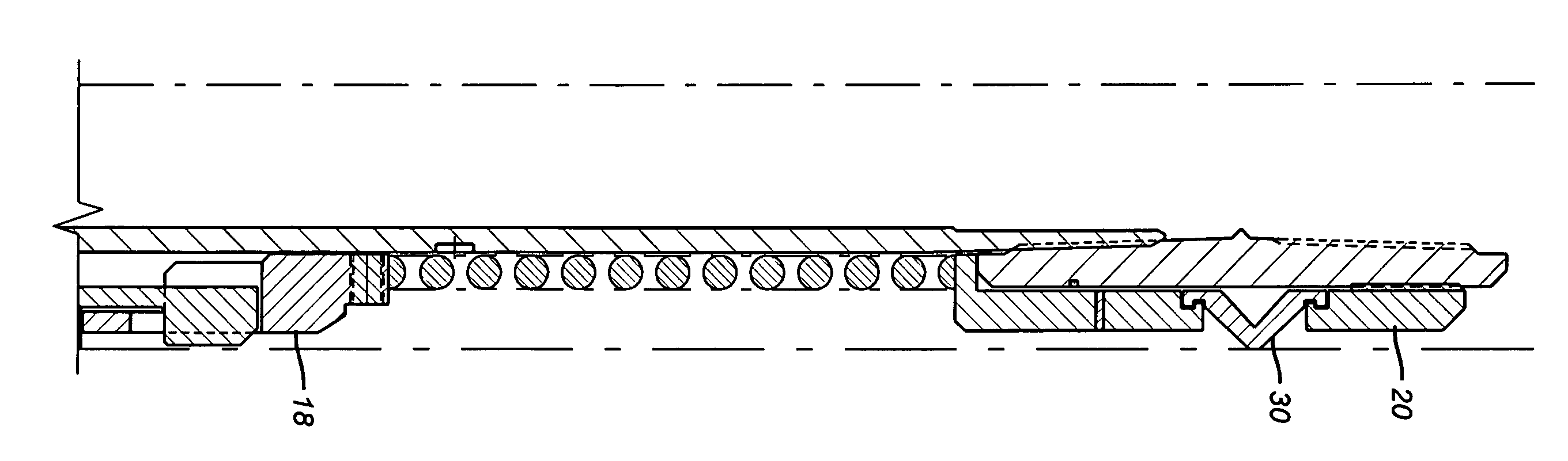
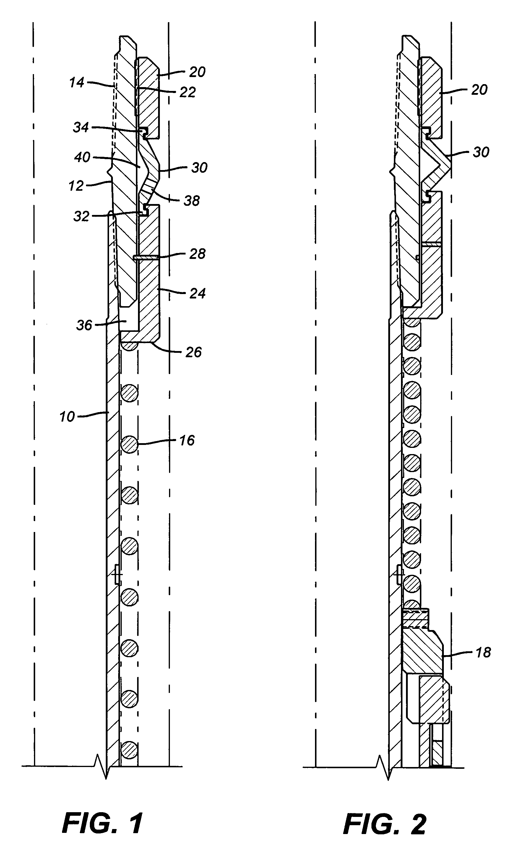
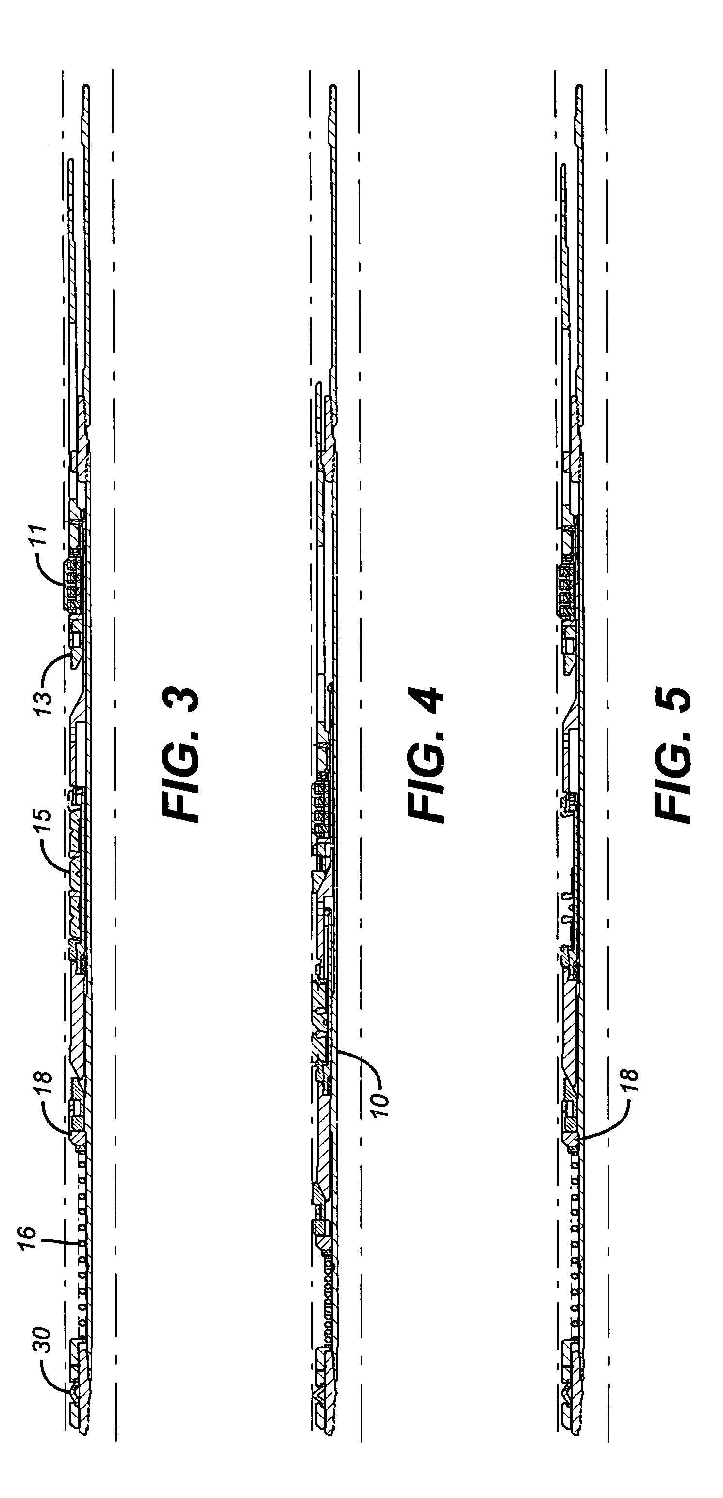
[0013]Those skilled in the art of mechanical set packers are presumed to be familiar with its major components and such components are depicted in the FIGS. 3-5. Typically, such packers have an outer housing that is temporarily supported in the wellbore by drag blocks 11, which are spring loaded dogs that catch on the surrounding tubular and provide temporary support for a mandrel 10 that is connected to a top sub 12 and supported by a tubing string (not shown) that is connected at thread 14 and continues up the well bore to surface. Typically, there is some type of j-slot mechanism between the outer housing and the mandrel 10 that lets the mandrel 10 be manipulated relative to the outer housing that is supported by the drag blocks. This mandrel manipulation occurs from surface by rotation of the tubing string.

[0014]In prior designs the spring 16 would bear on the top sub 12 on one end and on a slip assembly 18 shown in FIG. 2. The rotational manipulation of the mandrel 10 would bri...


PUM


Abstract

A debris barrier for a retrievable mechanical set packer is held retracted for run in. It is held spaced apart from upper slips and uses a spring bias that acts on the slips to keep them energized to also energize the barrier to the extended position to keep debris out of the upper slips when the packer is set. The debris barrier is preferably a sleeve that is axially compressed by the setting procedure to increase in diameter and span the gap between the packer mandrel and the set upper slips. Retrieving the packer is enabled by a retraction of the debris barrier as the upper slips are undermined with rotation and pickup force on the packer mandrel. The lack of a debris barrier could prevent retrieval of the packer in well bores where debris is present and has a tendency to settle around and more critically under the upper slips.

Description

FIELD OF THE INVENTION[0001]The field of the invention is debris barriers for retrievable downhole tools and more particularly for mechanically set packers.BACKGROUND OF THE INVENTION[0002]Packers are used downhole to isolate different zones. Some packers are made to be removed at a later time after being set in the well for what could be fairly long time periods. These packers are referred to as retrievable. They generally feature slips actuated by cones that are moved under the slips to move them out radially to support the packer. A sealing element assembly is between the upper and lower slips. In order to retrieve such packers the cone that wedges in a slip assembly has to be retracted from under the slip that it formerly wedged against a tubular. Usually, on mechanical set packers the mandrel is manipulated by tubing string rotation so that it pulls the cone out from under the upper slip assembly to allow the sealing element to relax as the packer extends so that it can then be...

Claims


Application Information

Patent Timeline
Patent Type & Authority Patents(United States)
IPC IPC(8): E21B23/06
CPCE21B33/1292
Inventor KOSSA, EDWARD J.RAMIREZ, RAFAEL
Owner BAKER HUGHES INC
Why Eureka
Try Eureka