Locking mechanisms for fixation devices and methods of engaging tissue
What is AI technical title?
AI technical title is built by Patsnap AI team. It summarizes the technical point description of the patent document.
a technology of locking mechanism and fixation device, which is applied in the field of medical methods, devices and systems, can solve the problems that the fixation device may not be able to close as far as, and achieve the effects of reducing frictional engagement, reducing frictional engagement of the inner surface, and restricting movemen
Inactive Publication Date: 2009-10-20
EVALVE
View PDF380 Cites 345 Cited by
Summary
Abstract
Description
Claims
Application Information
AI Technical Summary
This helps you quickly interpret patents by identifying the three key elements:
Problems solved by technology
Method used
Benefits of technology
Benefits of technology
[0024]Alternatively, the locking mechanism may comprises an interference element which is positionable along the moveable stud so that the interference element prevents movement of the moveable stud in at least a first direction by contacting a stationary surface of the fixation device. In some embodiments, the interference element comprises a locking sheath advanceable over the moveable stud so that the locking sheath prevents movement of the stud in the at least first direction by abutting against the stationary surface. In other embodiments, the moveable stud includes external grooves and the interference element comprises a lock nut mateable with the external grooves of the moveable stud so that the mated lock nut prevents movement of the stud in at least the first direction by abutting against the stationary surface.
[0025]It may be appreciated that the moveable stud may be comprised of a rigid material, such as a metal or plastic, or the moveable stud may be comprised of a flexible line, such as a suture. When the moveable stud comprises a flexible line, the locking mechanism may comprise an interference element which is positionable along the flexible line so that the interference element prevents movement of the flexible line in at least a first direction by contacting a stationary surface of the fixation device.
[0029]In a third aspect of the present invention, the fixation devices include an unlocking mechanism for disengaging the locking mechanism. In some embodiments, the unlocking mechanism comprises a harness, the harness adapted to disengage or reduce engagement of an engaging element from the moveable stud. For example, the harness may reduce frictional engagement a wedging element against the moveable stud.
[0034]In another aspect of the present invention, a locking mechanism is provided comprising a moveable stud coupled to a device, wherein movement of the stud actuates movement of a portion of a device to a desired position in a range from a first position to a second position, at least one element configured to engage the stud to restrict movement of the stud which locks the device in the desired position, and an unlocking mechanism configured to disengage the at least one element from the stud which allows movement of the stud. In some instances, the at least one element comprises a binding plate having a first end, a second end and a portion therebetween shaped to at least partially surround the stud, the binding plate positioned so that the portion at least partially surrounds the stud. The portion shaped to at least partially surround the stud may comprise an aperture, the binding plate positioned so that the stud passes through the aperture. In some embodiments, the locking mechanism further comprising a spring configured to force the aperture against the stud to restrict movement of the stud through the aperture. The unlocking mechanism may comprise a harness, the harness adapted to move the second end while the first end remains substantially stationary so as to reduce frictional engagement of the at least partially surrounding portion with the stud.
[0035]In some embodiments, the at least one element comprises at least one cam, the at least one cam pivotable to frictionally engage the stud to restrict movement thereof. The at least one cam may have an inward surface engageable with the stud and an outward surface connected with a spring which forces the inward surface against the stud to restrict movement of the stud. In some embodiments, the unlocking mechanism comprises at least one actuator attached to a pivot point on each of the at least one cams, the at least one actuator adapted to pivot the at least one cam about its pivot point to reduce frictional engagement of the inner surface with the stud.
Problems solved by technology
For example, if more tissue is captured or coapted by the fixation device, the fixation device may not be able to close as far than if less tissue is captured.
Method used
Image
Click on the blue label to locate the original text in one second.
Reading with bidirectional positioning of images and text.
Examples
Embodiment Construction
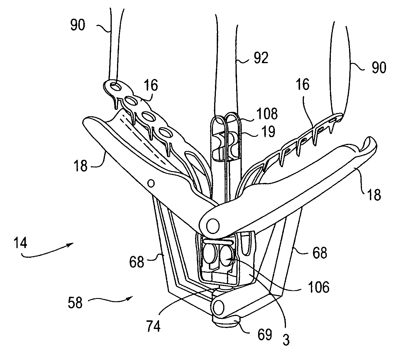
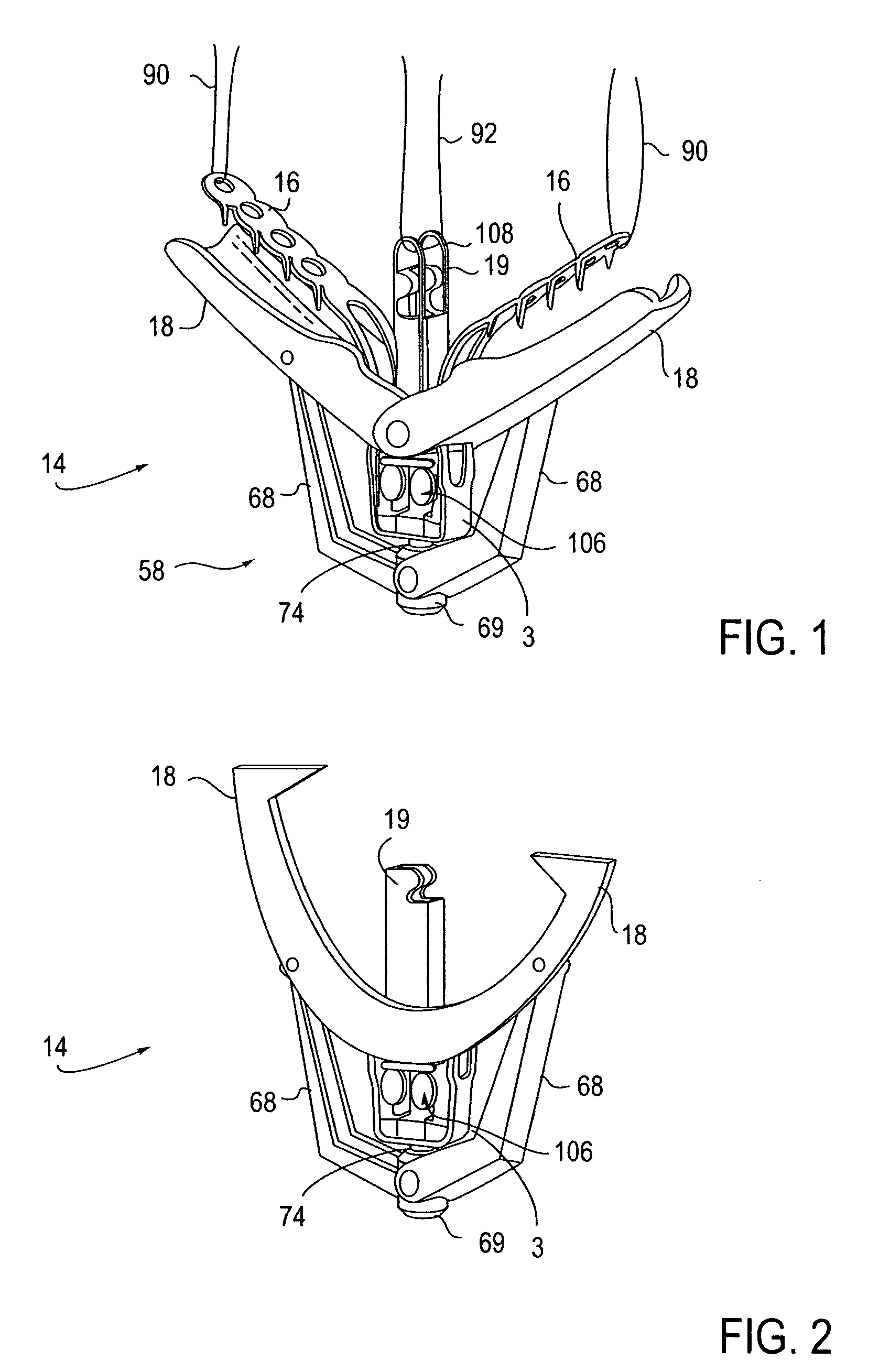
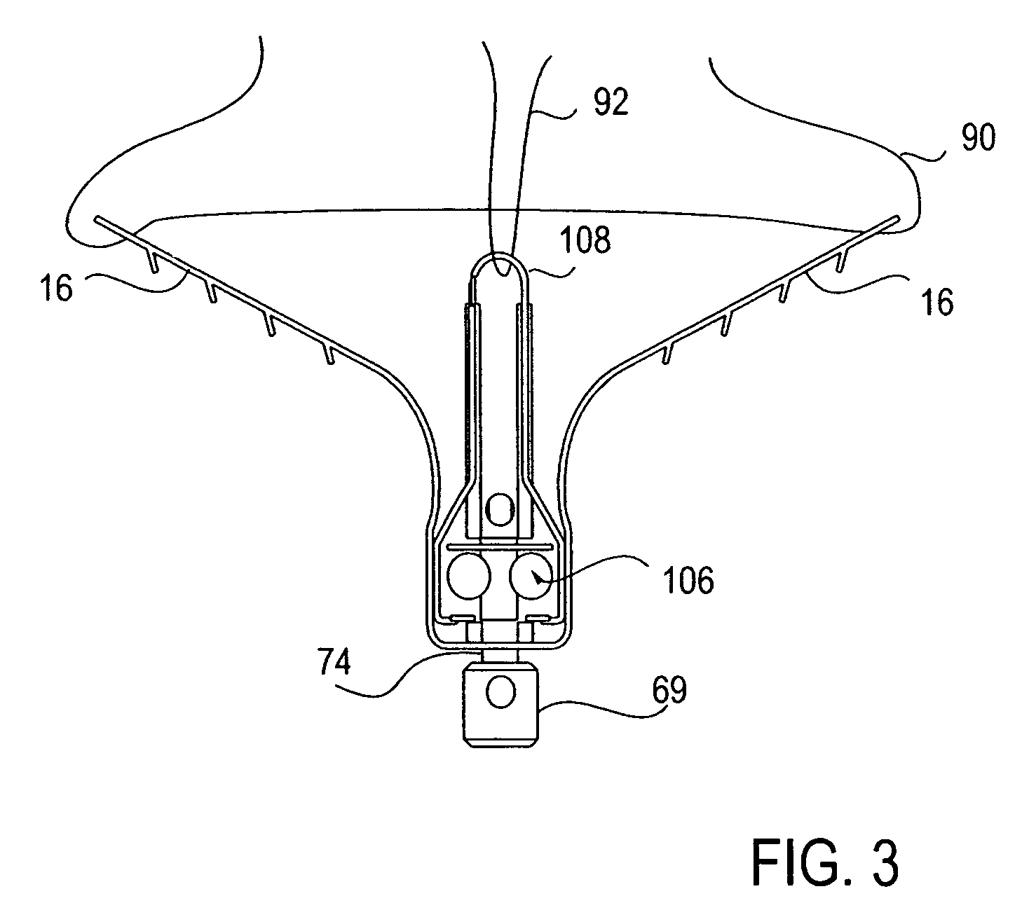
[0063]The fixation devices of the present invention provide for grasping, approximating and fixating tissues such as valve leaflets to treat cardiac valve regurgitation, particularly mitral valve regurgitation. In preferred embodiments, the fixation devices provide features that allow repositioning and removal of the device if so desired. Such removal would allow the practitioner to reapproach the valve in a new manner if so desired. Once the tissue has been satisfactorily approximated, the grasped tissue is typically fixed in place by maintaining grasping with the fixation device which is left behind as an implant.
[0064]The fixation device is releasably attached to a shaft of an interventional tool at its distal end. When describing the devices of the invention herein, “proximal” shall mean the direction toward the end of the device to be manipulated by the user outside the patient's body, and “distal” shall mean the direction toward the working end of the device that is positioned...
PUM
Abstract
Devices, systems and methods are provided for tissue approximation and repair at treatment sites. In particular, fixation devices are provided comprising a pair of elements each having a first end, a free end opposite the first end, and an engagement surface therebetween for engaging the tissue, the first ends being moveable between an open position wherein the free ends are spaced apart and a closed position wherein the free ends are closer together with the engagement surfaces generally facing each other. The fixation devices also include a locking mechanism coupled to the elements for locking the elements in place. The devices, systems and methods of the invention will find use in a variety of therapeutic procedures, including endovascular, minimally-invasive, and open surgical procedures, and can be used in various anatomical regions, including the abdomen, thorax, cardiovascular system, heart, intestinal tract, stomach, urinary tract, bladder, lung, and other organs, vessels, and tissues. The invention is particularly useful in those procedures requiring minimally-invasive or endovascular access to remote tissue locations, where the instruments utilized must negotiate long, narrow, and tortuous pathways to the treatment site.
Description
CROSS-REFERENCES TO RELATED APPLICATIONS[0001]This application claims the benefit and priority of U.S. Provisional Patent Application No. 60 / 571,217, filed May 14, 2004, and is a continuation-in-part of U.S. patent application Ser. No. 10 / 441,531, filed May 19, 2003 which is a continuation-in-part of, and claims the benefit of priority from U.S. Pat. No. 6,752,813, filed Jun. 27, 2001, which is a continuation-in-part of U.S. Pat. No. 6,629,534, filed Apr. 7, 2000, which claims the benefit of prior Provisional Application No. 60 / 128,690, filed on Apr. 9, 1999 under 37 CFR §1.78(a), the full disclosures of which are hereby incorporated herein by reference.[0002]In addition, U.S. patent application Ser. No. 10 / 441,531 is related to U.S. patent application Ser. No. 10 / 441,753, U.S. patent application Ser. No. 10 / 441,508, and U.S. patent application Ser. No. 10 / 441,687, all of which were filed on the same day (May 19, 2003), the full disclosures of which are incorporated herein by refere...
Claims
Application Information
Patent Timeline
Application Date:The date an application was filed.
Publication Date:The date a patent or application was officially published.
First Publication Date:The earliest publication date of a patent with the same application number.
Issue Date:Publication date of the patent grant document.
PCT Entry Date:The Entry date of PCT National Phase.
Estimated Expiry Date:The statutory expiry date of a patent right according to the Patent Law, and it is the longest term of protection that the patent right can achieve without the termination of the patent right due to other reasons(Term extension factor has been taken into account ).
Invalid Date:Actual expiry date is based on effective date or publication date of legal transaction data of invalid patent.

