
Augmented reality guided instrument positioning with depth determining graphics

a technology of depth determination and guided instruments, applied in the field of augmented reality, can solve the problems of confusion between the 3d perception of the observer and the inability of the (real) hand to occlude the virtual cube, and the lack of 3d information

Inactive Publication Date: 2009-10-20
SIEMENS MEDICAL SOLUTIONS USA INC
View PDF5 Cites 285 Cited by
  • Summary
  • Abstract
  • Description
  • Claims
  • Application Information

AI Technical Summary

Benefits of technology

[0015]The problems stated above, as well as other related problems of the prior art, are solved by the present inv

Problems solved by technology

Disadvantageously, this 3D information is usually not available and, thus, the virtual objects are simply superimposed onto the image of the real scene.
The inability of the (real) hand to occlude the virtual cube confuses the 3D perception of the observer.

Method used


Image

  • Augmented reality guided instrument positioning with depth determining graphics
  • Augmented reality guided instrument positioning with depth determining graphics
  • Augmented reality guided instrument positioning with depth determining graphics

Examples


Embodiment Construction

[0048]The present invention is directed to a method and apparatus for augmented reality guided instrument positioning with depth determining graphics.

[0049]It is to be understood that the present invention may be implemented in various forms of hardware, software, firmware, special purpose processors, or a combination thereof. Preferably, the present invention is implemented as a combination of hardware and software. Moreover, the software is preferably implemented as an application program tangibly embodied on a program storage device. The application program may be uploaded to, and executed by, a machine comprising any suitable architecture. Preferably, the machine is implemented on a computer platform having hardware such as one or more central processing units (CPU), a random access memory (RAM), and input / output (I / O) interface(s). The computer platform also includes an operating system and microinstruction code. The various processes and functions described herein may either b...


PUM


Abstract

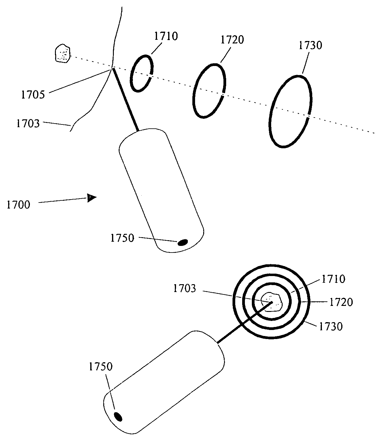
There is provided a method for augmented reality guided instrument positioning. At least one graphics proximity marker is determined for indicating a proximity of a predetermined portion of an instrument to a target. The at least one graphics proximity marker is rendered such that the proximity of the predetermined portion of the instrument to the target is ascertainable based on a position of a marker on the instrument with respect to the at least one graphics proximity marker.

Description

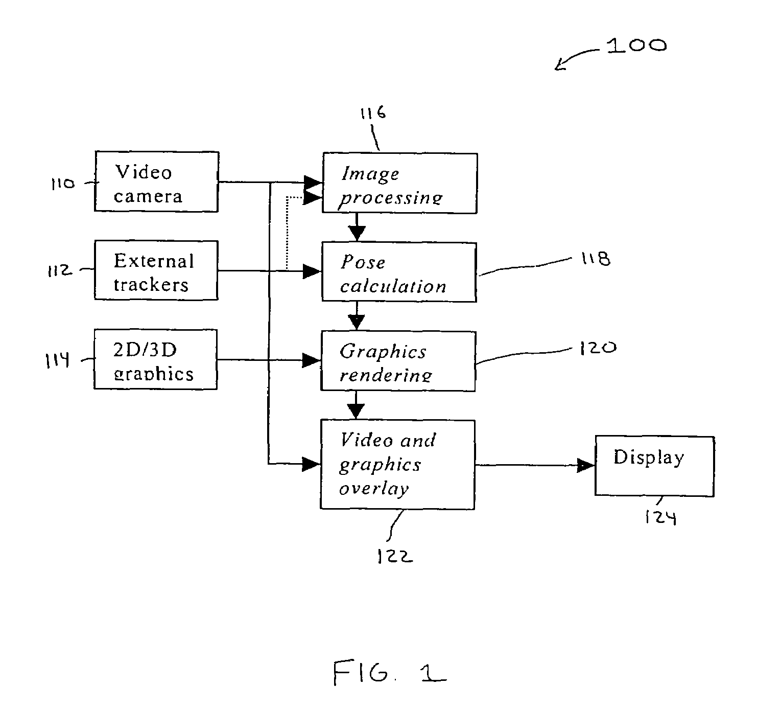
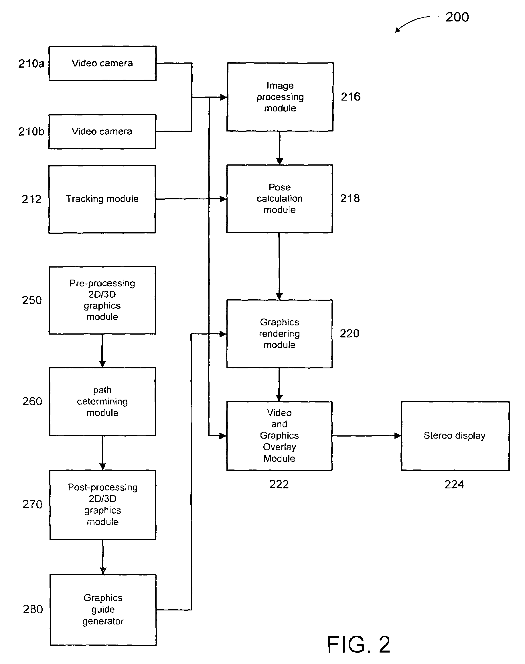
BACKGROUND[0001]1. Technical Field[0002]The present invention generally relates to augmented reality and, in particular, to a method for augmented reality guided instrument positioning with depth determining graphics.[0003]2. Background Description[0004]Augmented reality, also commonly referred to as augmented vision or augmented reality vision, augments an observer's view of the real world by superimposing computer generated graphical information. This information may be as simple as a text label attached to some object in the scene, or as complex as a 3D model of a patient's brain derived from an MRI scan and aligned to the real view of the person's head.[0005]The observer may observe a real scene directly with his or her eyes, with the additional graphical information being blended therewith via a semi-transparent display located between the observer and the real scene. Such a display device can be, for example, a see-through head mounted display.[0006]The display can also be opa...

Claims


Application Information

Patent Timeline
IPC IPC(8): G09G5/00G06F3/00G06F3/01G06F3/033G06F3/048
CPCG06F3/04815G06F3/011
Inventor SAUER, FRANK
Owner SIEMENS MEDICAL SOLUTIONS USA INC
Learn More