
Signal transmission apparatus

a signal transmission and signal technology, applied in the field of signal transmission apparatus, can solve the problems of increasing delay time, band loss, and difficulty in stably controlling the many audio amplifiers and other audio equipment involved in the network

Inactive Publication Date: 2009-10-20
YAMAHA CORP
View PDF13 Cites 140 Cited by
  • Summary
  • Abstract
  • Description
  • Claims
  • Application Information

AI Technical Summary

Benefits of technology

[0027]Preferably, the control apparatus further comprises a setting section that sets an operation mode for determining whether to issue the warning or not, such that the warning is issued on the condition that the operation mode is set to issue the warning and the mismatch is determined by the determination section.
[0028]In a fifth aspect of the invention, a signal transmission apparatus is connected to a network as one node among a plurality of nodes involved in the network which is provided with an audio signal transmission period for transmitting a plurality of channels of audio signals each transmission cycle and a control data transmission period for transmitting control data of the plurality of the nodes each control cycle by using an idle time period other than the audio signal transmission period. The signal transmission apparatus comprises a first determination section that determines whether a predetermined time period has elapsed since the start of a current control cycle, a second determination section that determines whether the transmission of the control data from all the nodes is completed in the current control cycle, and a cycle starting section that transmits a start signal to all of the nodes for starting a new control cycle when results of determination by the first and second determination sections are both affirmative. Preferably, said one node is selected as a sole commander node among the plurality of the nodes connected to the network for commanding all the nodes. Preferably, the plurality of the nodes involved in the network sequentially transmit control data according to a predetermined transmission order within the control data transmission period, such that said one node transmits the control data at a timing when said one node comes in turn of the predetermined transmission order.
[0029]Another signal transmission apparatus is connected to a network as one node among a plurality of nodes which treat various physical quantities in processing of audio signals, the network being provided with an audio signal transmission period for transmitting a plurality of channels of audio signals each transmission cycle and a control data transmission period for transmitting control data of the plurality of the nodes each control cycle by using an idle time period other than the audio signal transmission period. The signal transmission apparatus comprises a creating section that creates instruction data which instructs another node to transmit a particular one of the physical quantities treated by said another node, a transmitting section that transmits the control data including the created instruction data to said another node through the network, and a receiving section that receives the control data containing a value of the particular physical quantity from said another node. Preferably, said one node is selected as a sole commander node among the plurality of the nodes connected to the network for collecting the values of the various physical quantities treated in the plurality of the nodes.
[0030]A further signal transmission apparatus is connected to a network as one node among a plurality of nodes which treat various physical quantities in processing of audio signals, the network being provided with an audio signal transmission period for transmitting a plurality of channels of audio signals each transmission cycle and a control data transmission period for transmitting control data of the plurality of the nodes each control cycle by using an idle time period other than the audio signal transmission period. The signal transmission apparatus comprises a receiving section that receives the control data containing instruction data form another node, the instruction data instructing said one node to transmit a first physical quantity and a second physical quantity treated by said one node, and a transmitting section that transmits the control data containing values of the first physical quantity and second physical quantity, such that the value of the first physical quantity is transmitted every control cycle, while the value of the second physical quantity is transmitted at a control cycle immediately after a variation in the value of the second physical quantity is detected in said one node. Preferably, the first physical quantity is variable at a high frequency as compared to the second physical quantity, and the second physical quantity is variable at a low frequency as compared to the first physical quantity. Preferably, the plurality of the nodes involved in the network sequentially transmit control data according to a predetermined transmission order within the control data transmission period, such that said one node transmits the control data at a timing when said one node comes in turn of the predetermined transmission order.

Problems solved by technology

However, the occurrence of a collision actually causes band losses due to arbitration.
However, since the band for serial communication is narrow by definition, the transmission of control data causes a problem of increasing delay time.
In addition, since the delay time depends on the number of bundles of audio data, it is difficult to stably control many audio amplifiers and other audio equipment involved in the network, and to stably collect status data of the amplifiers and other audio equipment from the network.
This increases the number of cables used and hence causes a problem of increasing the trouble in building up the sound system.

Method used


Image

  • Signal transmission apparatus
  • Signal transmission apparatus
  • Signal transmission apparatus

Examples


Embodiment Construction

1. Structure of Embodiment

1.1. General Structure

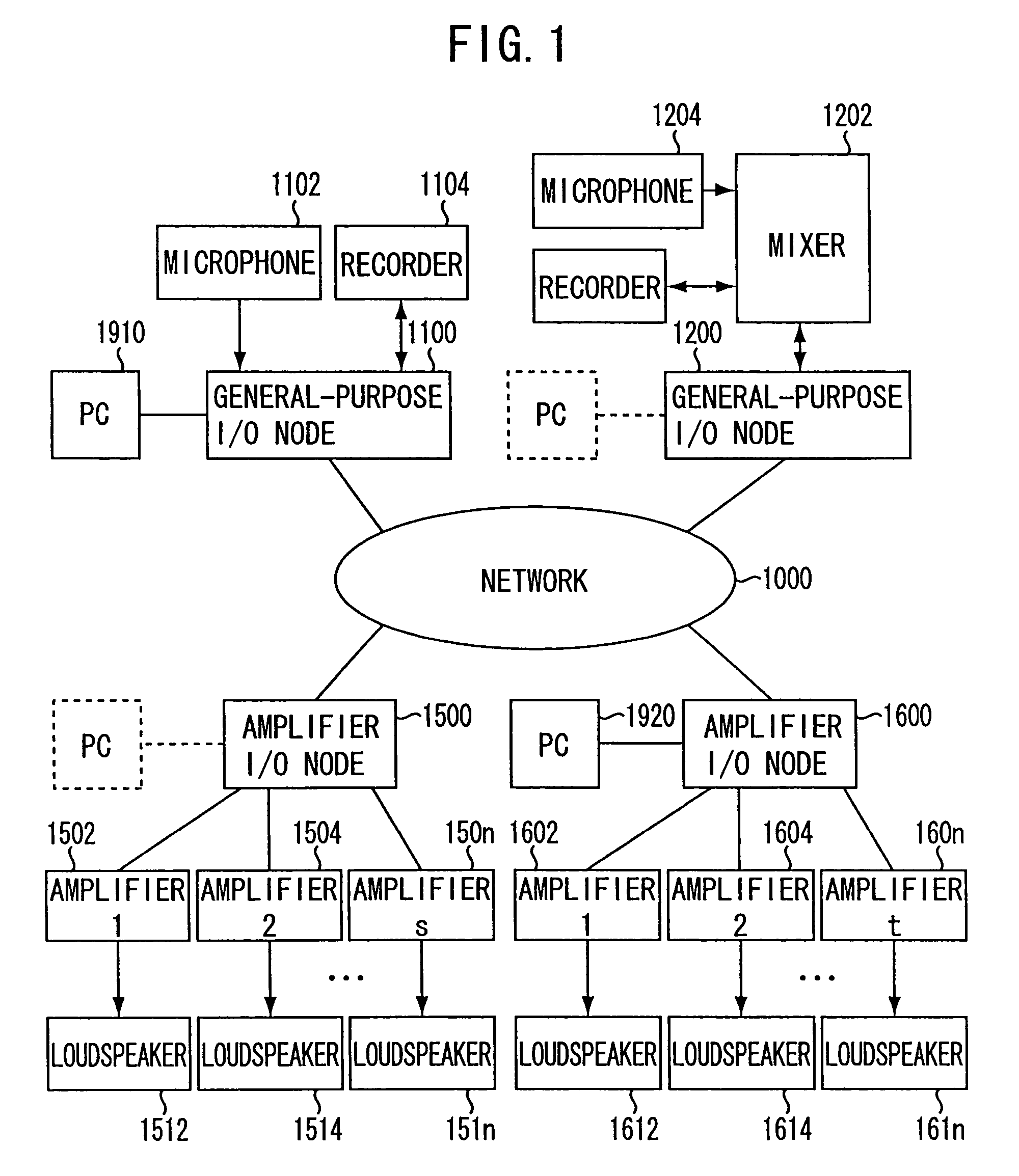
[0041]The general structure of a signal transmission system according to one preferred embodiment of the present invention will now be described with reference to FIG. 1.

[0042]1000 designates an Ethernet network (where Ethernet is a registered trademark), which transmits packets among a plurality of nodes connected to the network 1000. The nodes connected to the network 1000 are broadly divided into two categories: “general-purpose I / O node” and “amplifier I / O node”. The former is a node type capable of outputting and inputting audio data through the network 1000, and the latter is a node type which can only receive audio data from the network 1000. On the network 1000, it is possible to connect up to “eight” general-purpose I / O nodes and “16” amplifier I / O nodes.

[0043]In the example shown, “two” general-purpose I / O nodes 1100 and 1200 and “two” amplifier I / O nodes 1500 and 1600 are connected to the network 1000. Then, a microphone 110...


PUM


Abstract

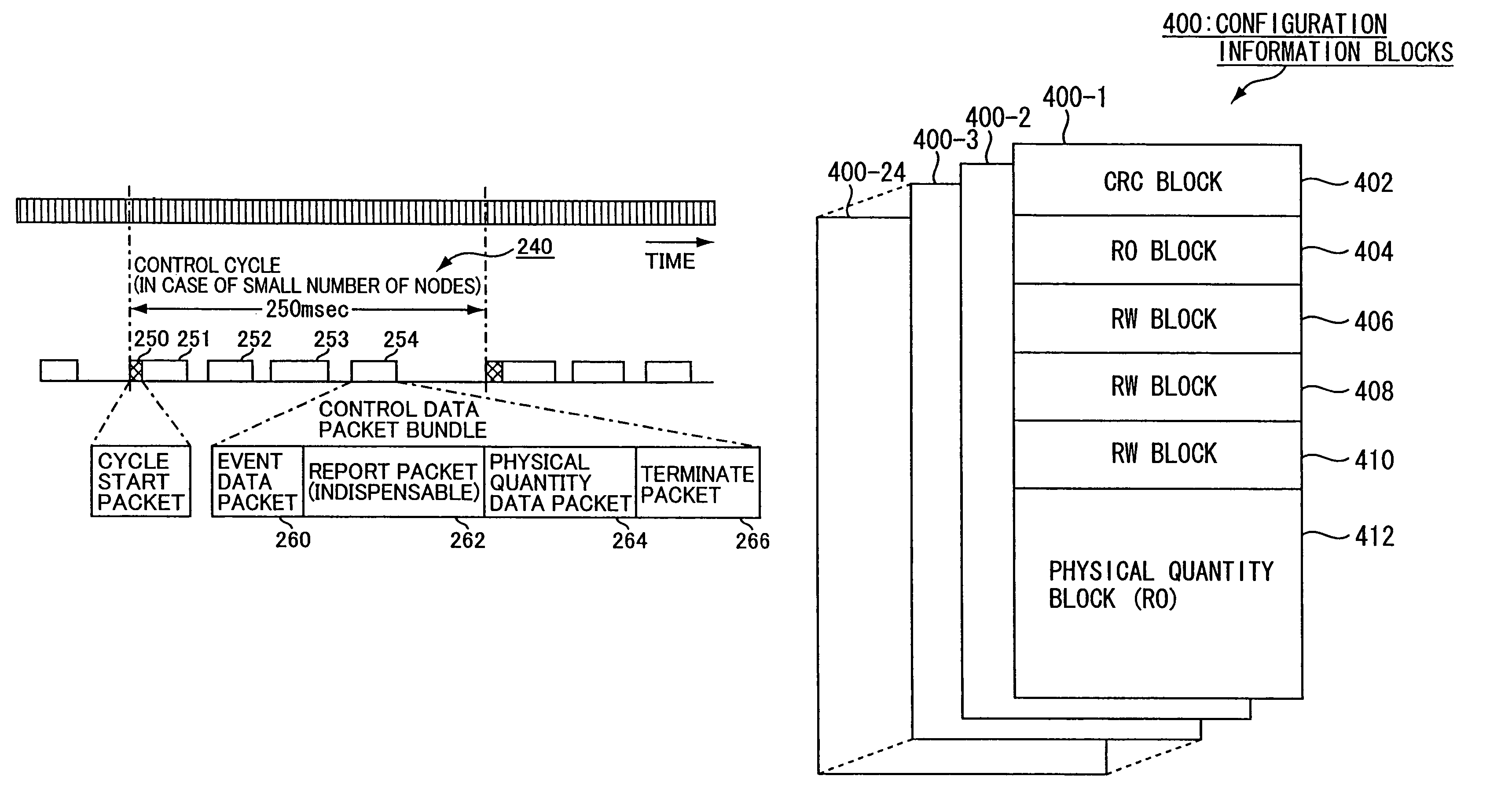
A signal transmission apparatus is connected to a network as one node among a plurality of nodes involved in the network which is provided with an audio signal transmission period for transmitting a plurality of channels of audio signals each transmission cycle and a control data transmission period for transmitting control data of the plurality of the nodes each control cycle by using an idle time period other than the audio signal transmission period. In the signal transmission apparatus, a storage section stores configuration information of the one node. A transmitting section transmits the control data including an error checking code of the configuration information. A receiving section receives request data from another node, the request data requesting the one node for transmission of an information block of the configuration information. A control section controls the transmitting section to transmit the information block in response to the request data.

Description

BACKGROUND OF THE INVENTION[0001]1. Technical Field of the Invention[0002]The present invention relates to a signal transmission apparatus adapted for use in a system for transmitting an audio signal through a network while controlling audio amplifiers, mixers and other audio equipment connected to the network.[0003]2. Prior Art[0004]In a sound system used at a big concert hall and the like, multiple channels of audio signals generated by a mixing system and the like are sounded from many loudspeakers through many amplifiers. Since the number of cables will become enormous if a cable for audio signal transmission is installed for each individual channel, it is desirable to convert multiple channels of audio signals into audio data packets and to transmit them through a digital network.[0005]The technology of CobraNet™ is known as a protocol method of transmitting multiple channels of audio data in real time through a network of a CSMA / CD (Carrier Sense Multiple Access with Collision...

Claims


Application Information

Patent Timeline
Patent Type & Authority Patents(United States)
IPC IPC(8): H04L12/28G06F11/00G06F7/02H04J3/12H04J3/24H04H60/04H04L1/00H04L29/06
CPCH04H60/04H04L29/06H04L1/0072H04L1/0061H04L9/40
Inventor OCHI, MITSUNORINISHIKORI, TAKU
Owner YAMAHA CORP
Learn More