
Local power consumption load control

a load control and local power consumption technology, applied in the direction of process and machine control, process/dynamic balance measurement, instruments, etc., can solve the problems of increasing energy consumption, increasing the complexity of the process of supplying energy, and increasing the energy consumption of households

Active Publication Date: 2009-10-20
ITRON
View PDF51 Cites 66 Cited by
  • Summary
  • Abstract
  • Description
  • Claims
  • Application Information

AI Technical Summary

Benefits of technology

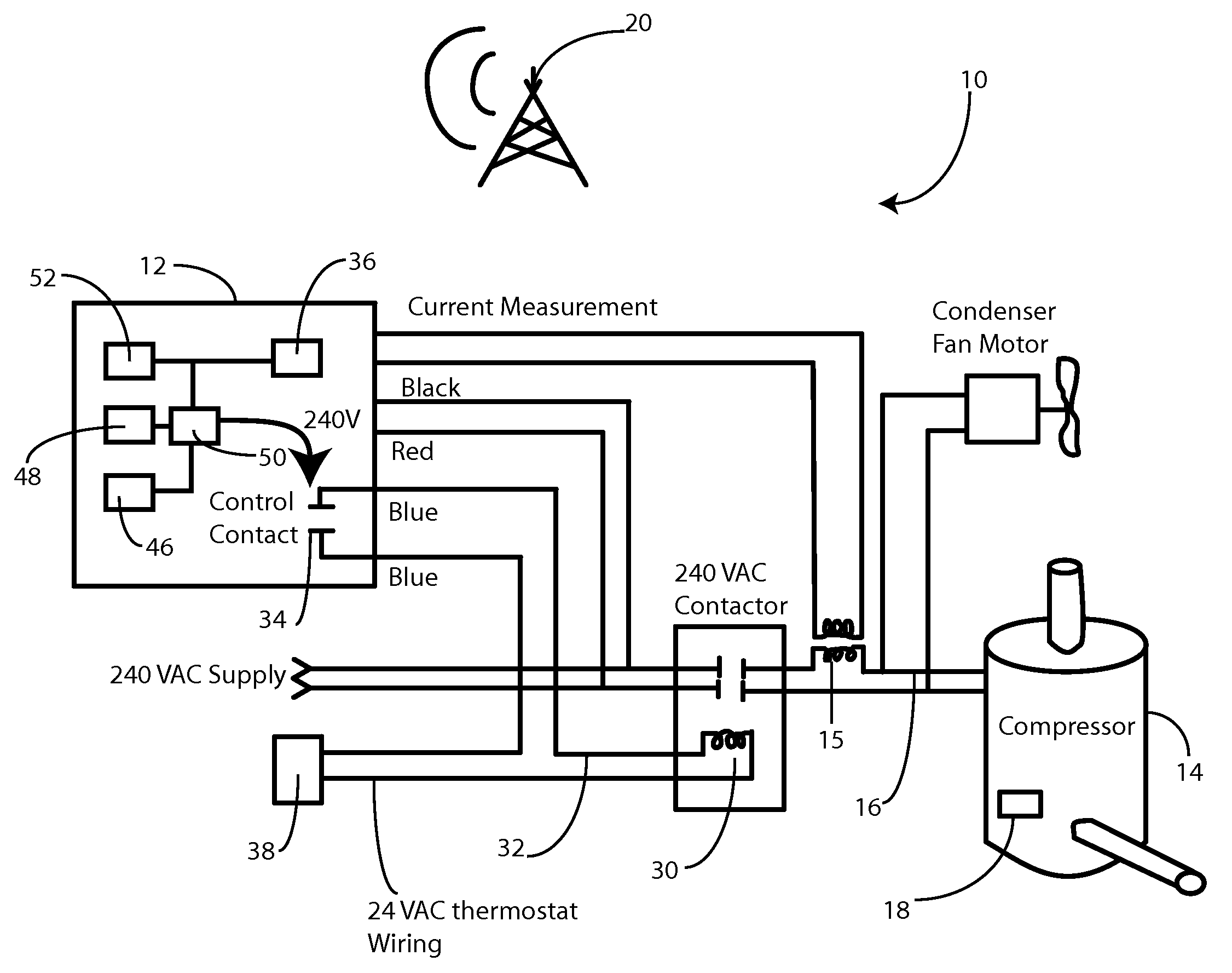
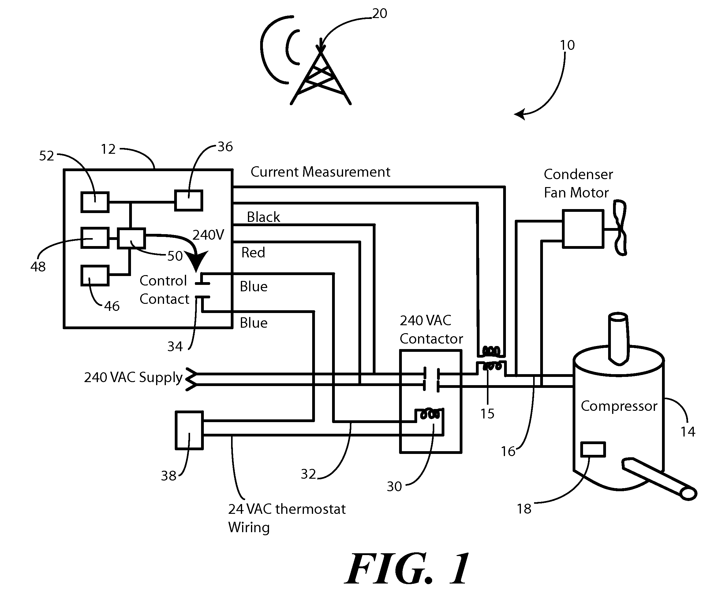
The present invention relates to a system and method for controlling the load of an appliance, such as an air conditioning compressor or furnace, to reduce energy consumption and achieve power consumption reduction. The system includes a control unit with a current sensing transformer that is connected to the control wire between a control switch and the appliance. The control unit monitors the current and adjusts the load control to achieve a certain level of demand relief. The system can provide a number of kilowatts of demand relief and can be used in conjunction with an energy provider to manage energy consumption. The invention helps to improve the efficiency of energy usage and can help to avoid failures and blackouts.

Problems solved by technology

As the cost of energy continues to rise, heating and cooling a home has become a complicated activity.
The process of supplying energy has become more complex as well.
While divesture and competition helps the consumer regarding price, without proper coordination between the various entities, problems can arise.
For example, on a hot summer day, consumers may demand unusually large amounts of energy to cool their homes.
While generators may be able to deliver this energy, if the transmission system is not configured to handle such large quantities of energy, failures, including blackouts, can occur.

Method used


Image

  • Local power consumption load control
  • Local power consumption load control
  • Local power consumption load control

Examples


Embodiment Construction

[0013]Before describing in detail embodiments that are in accordance with the present invention, it should be observed that the embodiments reside primarily in combinations of method steps and apparatus components related to limiting energy demand by a number of kilowatts. Accordingly, the apparatus components and method steps have been represented where appropriate by conventional symbols in the drawings, showing only those specific details that are pertinent to understanding the embodiments of the present invention so as not to obscure the disclosure with details that will be readily apparent to those of ordinary skill in the art having the benefit of the description herein.

[0014]It will be appreciated that embodiments of the invention described herein may be comprised of one or more conventional processors and unique stored program instructions that control the one or more processors to implement, in conjunction with certain non-processor circuits, some, most, or all of the funct...


PUM


Abstract

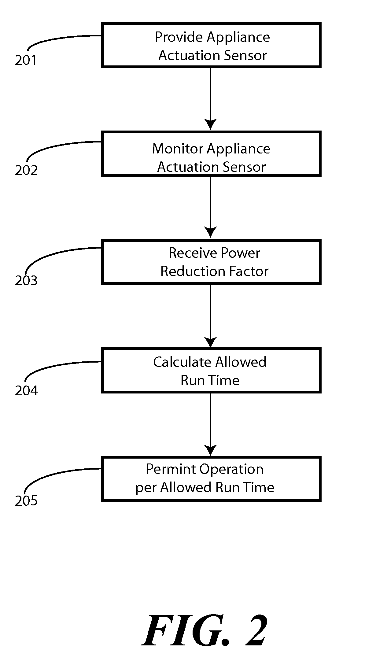
A method and system for curtailing energy consumption of an appliance, such as an air conditioning compressor or heat pump, is provided. A control unit stores information relating to the load, which may include a connected load value, such as a power consumption value or efficiency rating. The control unit then monitors the appliance to determine when the appliance is calling for energy. Upon receiving an energy reduction value from a remote source, the control unit then calculates a permitted run time from the energy reduction value and the connected load value. The control unit, through a switch, then permits the appliance to be operable only for the permitted run time so as to reduce power consumption by a predetermined amount.

Description

CROSS REFERENCE TO PRIOR APPLICATIONS[0001]This application claims priority and benefit under 35 U.S.C. §119(e) from U.S. Provisional Application No. 60 / 714,801, filed Sep. 7, 2005, which is incorporated by reference for all purposes.BACKGROUND[0002]1. Technical Field[0003]This invention relates generally to load control systems, and more specifically to a method and apparatus for reducing running time of a load, such as an air compressor or furnace, to achieve a power consumption reduction.[0004]2. Background Art[0005]As the cost of energy continues to rise, heating and cooling a home has become a complicated activity. When natural gas, heating oil and electric power were plentiful and inexpensive, one may simply have set the thermostat on 78 in the summer and 68 in the winter to adequately heat and cool a house. Under such a plan, they may only touch the thermostat twice in a year.[0006]The process of supplying energy has become more complex as well. With deregulation of various u...

Claims


Application Information

Patent Timeline
Patent Type & Authority Patents(United States)
IPC IPC(8): G05F1/66
CPCG01R22/063H02J3/14Y02B70/3225Y04S20/244Y04S20/222Y04S20/224Y02B70/3275H02J2310/14Y02B70/30Y04S20/242
Inventor MIYAJI, WENDELL M.
Owner ITRON
Learn More