
Oxygen sensor output correction apparatus for internal combustion engine

a technology of output correction and internal combustion engine, which is applied in the direction of machines/engines, liquid/fluent solid measurement, process and machine control, etc., can solve the problems of sensor current error and decrease in the accuracy of the under-atmosphere correction mod

Active Publication Date: 2009-10-20
DENSO CORP
View PDF11 Cites 7 Cited by
  • Summary
  • Abstract
  • Description
  • Claims
  • Application Information

AI Technical Summary

Benefits of technology

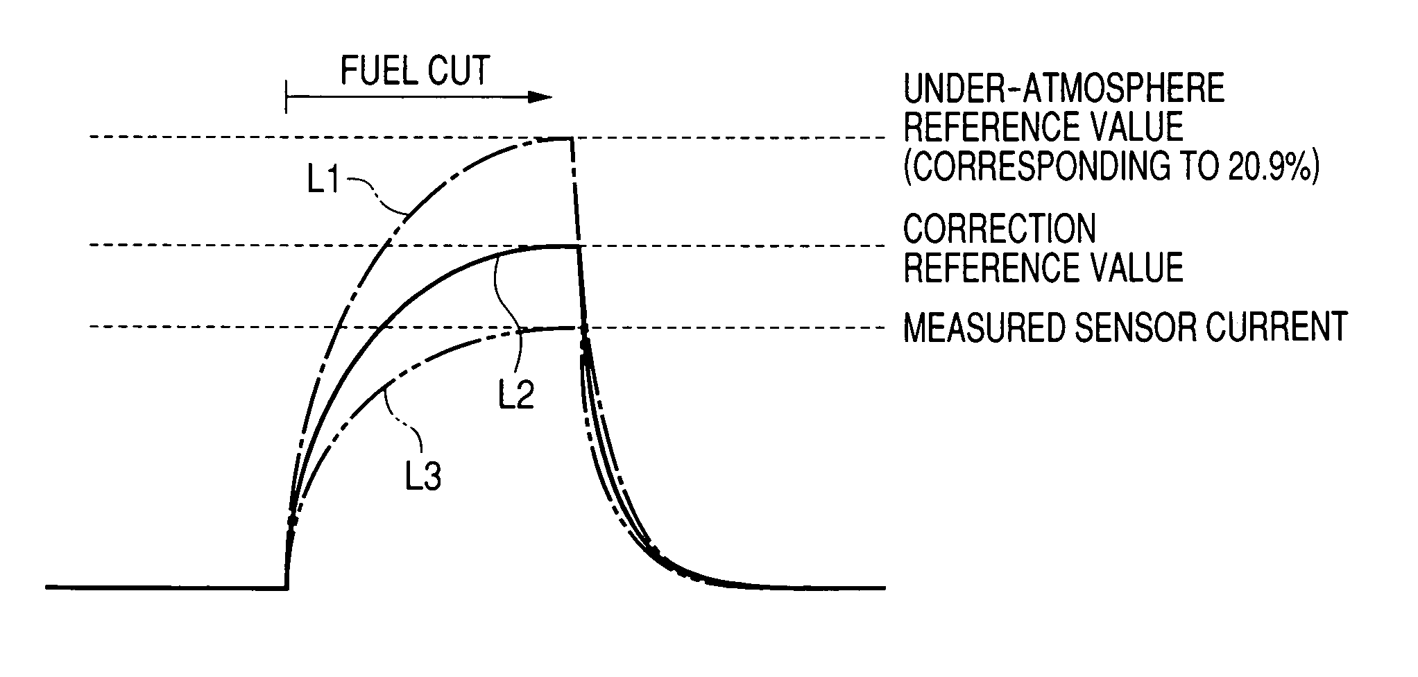
[0017]The oxygen concentration-corresponding output determining circuit may determine the oxygen concentration-corresponding output based on the given parameter, as determined by the oxygen concentration-correlating parameter determining circuit, and a speed of the engine after the start of the fuel cut event. Specifically, a change in speed of the engine during the fuel cut event usually results in a change in mode in which the concentration of oxygen in the exhaust pipe varies. For instance, as the speed of the engine increases, the concentration of oxygen changes to that in the atmospheric air quickly. Conversely, as the speed of the engine decreases, the concentration of oxygen changes slowly. In other words, the rate of change in concentration of oxygen depends upon the integrated amount of intake air charged into the engine. An error in correcting the output of the oxygen sensor arising from such a change in concentration of oxygen depending upon the integrated amount of intake air may, therefore, be eliminated by determining the oxygen concentration-corresponding output using the speed of the engine after the start of the fuel cut event as an additional parameter.

Problems solved by technology

When the concentration of oxygen in the exhaust pipe does not reach that in the fresh air until the completion of the fuel cut event, it will result in an error in the sensor current and a decrease in accuracy in the under-atmosphere correction mode.

Method used


Image

  • Oxygen sensor output correction apparatus for internal combustion engine
  • Oxygen sensor output correction apparatus for internal combustion engine
  • Oxygen sensor output correction apparatus for internal combustion engine

Examples


Embodiment Construction

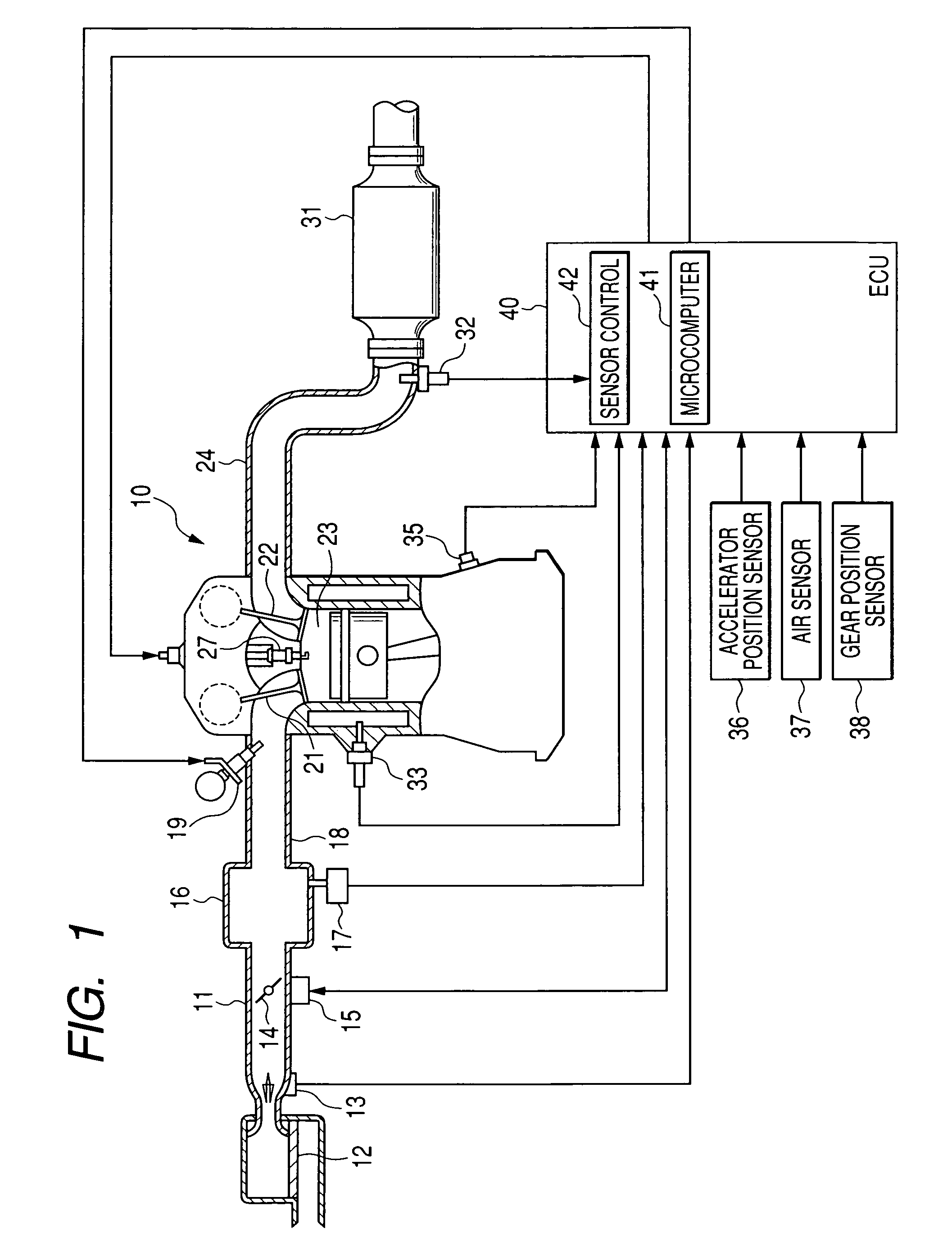
[0037]Referring to the drawings, wherein like reference numbers refer to like parts in several views, particularly to FIG. 1, there is shown an engine control system according to the first embodiment of the invention which is designed to control an operation of an automotive multi-cylinder internal combustion engine 10. The engine control system is implemented by an electronic control unit (ECU) 40 and works to control the quantity of fuel to be injected into the engine 10 and the ignition timing of spark plugs installed in the engine 10.

[0038]The engine 10 has an intake pipe 11 and an exhaust pipe 24 connected thereto. An air cleaner 12 is installed in the intake pipe 11. An air flow meter 13 is disposed downstream of the air cleaner 12 to measure the flow rate of intake air charged into the engine 10. A throttle valve 14 is disposed downstream of the air flow meter 13. The throttle valve 14 is closed or opened by a throttle actuator 15 such as a DC motor. The degree of opening or ...


PUM


Abstract

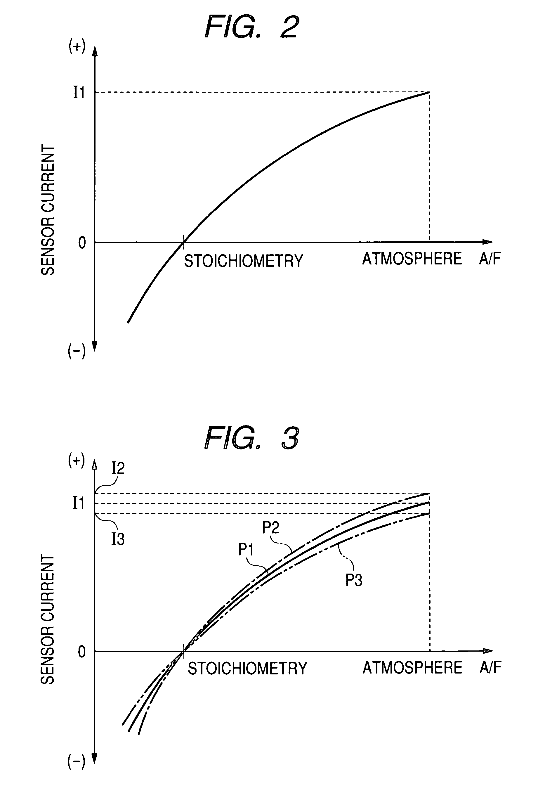
A correction apparatus for correcting an error in an output of an oxygen sensor such as an A / F sensor installed in an exhaust pipe of an internal combustion engine to measure the concentration of oxygen contained in exhaust gas. The apparatus works to determine a given parameter correlating with an actual concentration of oxygen within the exhaust pipe after start of a fuel cut event and also determine an oxygen concentration-corresponding output based on the given parameter which is a parameter corresponding to an output of the oxygen sensor considered to represent the actual concentration of oxygen correctly. The apparatus samples an output of the oxygen sensor during the fuel cut event and determines a correction factor based on the sampled output of the oxygen sensor and the oxygen concentration-corresponding output for use in correcting an output of the oxygen sensor when the engine is undergoing no fuel cut.

Description

CROSS REFERENCE TO RELATED DOCUMENT[0001]The present application claims the benefit of Japanese Patent Application No. 2007-109613 filed on Apr. 18, 2007, the disclosure of which is totally incorporated herein by reference.BACKGROUND OF THE INVENTION[0002]1. Technical Field of the Invention[0003]The present invention relates generally to an oxygen sensor output correction apparatus for an internal combustion engine which is designed to cut a supply of fuel into the engine to place an oxygen sensor in the atmosphere or fresh air within an exhaust pipe and sample an output of the oxygen sensor to determine a correction factor for use in correcting or compensating for an error in the output.[0004]2. Background Art[0005]There are various techniques for installing an oxygen sensor in an exhaust pipe of an internal combustion engine and sampling an output therefrom indicating the concentration of oxygen contained in exhaust emissions to perform given control tasks for improving the quanti...

Claims


Application Information

Patent Timeline
Patent Type & Authority Patents(United States)
IPC IPC(8): F02D41/14
CPCF01N9/00F02D41/123F02D41/1448F02D41/2474F02D41/1455Y02T10/47F02D41/18F02D41/2454Y02T10/40
Inventor KAWASE, TOMOOKUROKAWA, EIICHIMASUKO, TAKAHITO
Owner DENSO CORP
Learn More