
Method of manufacturing doped superconducting materials

Active Publication Date: 2009-10-27
THE BOEING CO +2
View PDF4 Cites 2 Cited by
  • Summary
  • Abstract
  • Description
  • Claims
  • Application Information

AI Technical Summary

Benefits of technology

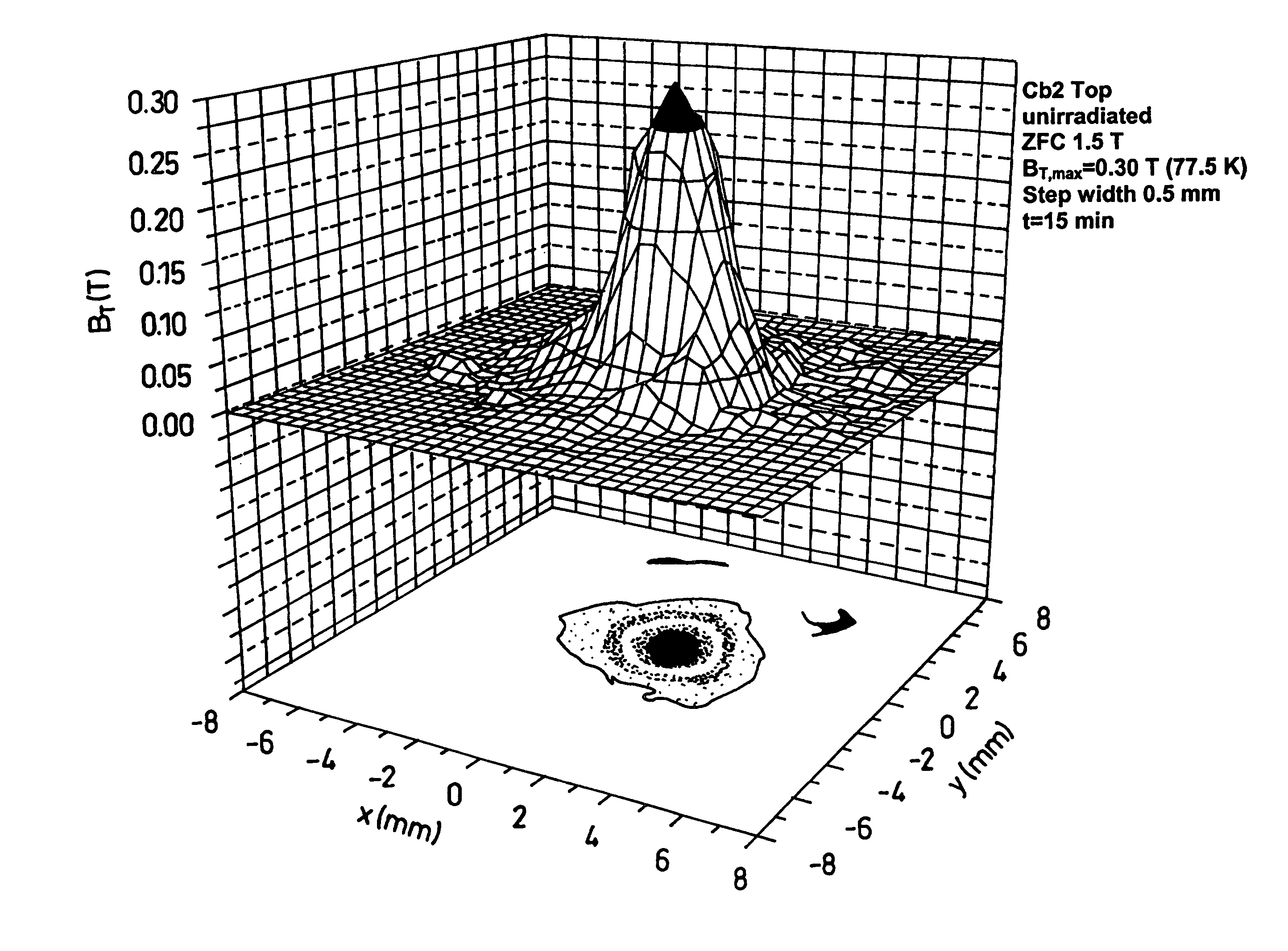
[0045]It has been found that the effect of adding XwBaxCuyLtOz particles to XaBabCucOd provides (1) that the size and number of dopant-containing particles can be pre-determined for the resultant crystal, before the crystal is formed; (2) superior refinement of the inclusions within the resultant crystal is effected to effect stronger magnetic fields within the structure, compared to crystals produced by known uranium-doping processes; (3) that the top seed processing procedure is simplified and accelerated compared to known processes; and (4) temperature of the crystal growing process can be optimised, and pre-planned, leading to superior quality, and superior effect, crystals.

Problems solved by technology

Furthermore, using processes such as top-seed melt processing to produce the uranium-doped crystals by adding UO2, is relatively difficult and the conditions for processing need to be set within fairly limited range in order for the UO2 and X—Ba—Cu—O crystals to be able to tolerate the required temperatures and times in which to form second phase particles within the final crystal.

Method used


Image

  • Method of manufacturing doped superconducting materials
  • Method of manufacturing doped superconducting materials
  • Method of manufacturing doped superconducting materials

Examples


example 1

[0055]An X—Ba—Cu—U—O material having a formula Y2Ba4CuUOz (hereinafter “DU”) was synthesised by conventional techniques. Particles of Y2BaCuO5 (Y-211) were synthesised along with particles of YBa2Cu3O7 (Y-123 particles), by a conventional solid state reaction technique.

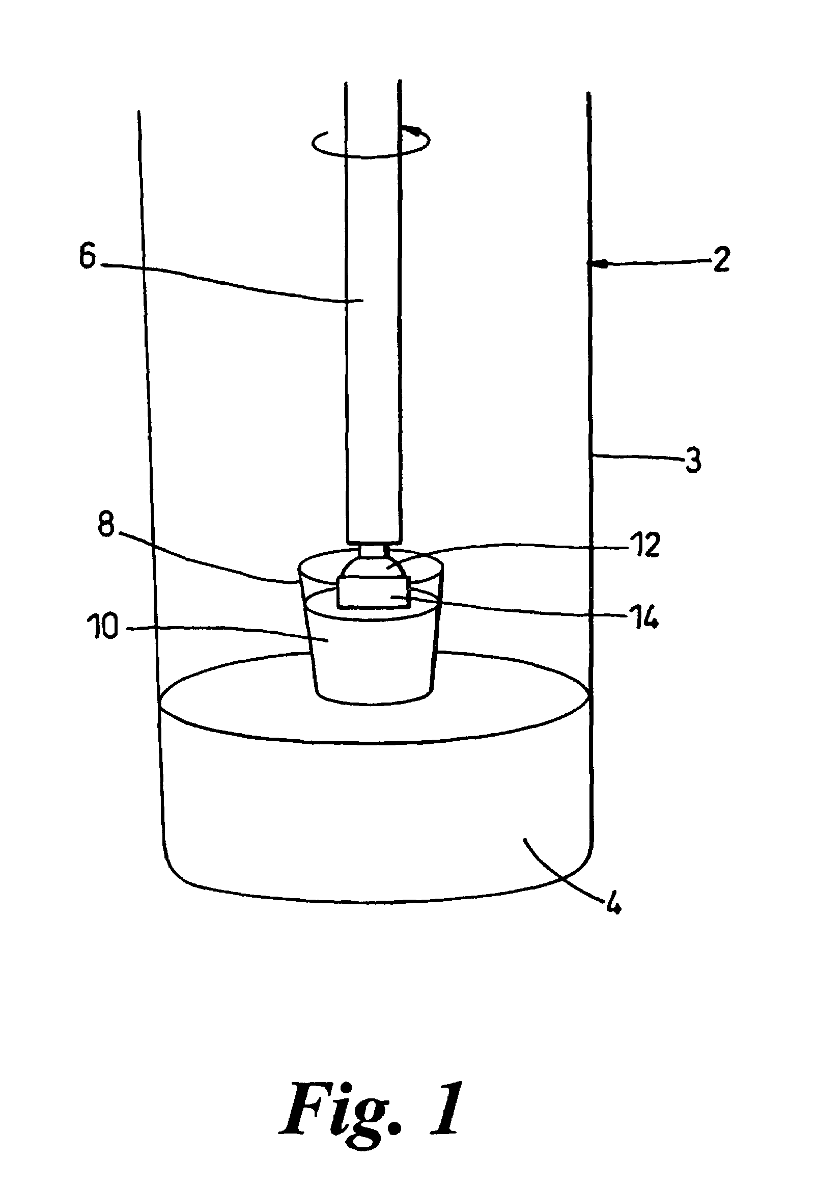
[0056]The Y-123, Y-211 and DU powdered particles were, pressed into a compact pellet placed in the melt receptacle 10, and placed on the pedestal 4 of the top-seed melt apparatus 2 shown in FIG. 1. The Y-123, Y-211 and DU particles were in the following proportions: Y-123 70 mol %, Y-211 30 mol % and 0.5% w / w DU.

[0057]The powder constituents in the melt receptacle 10 were heated to a temperature of 1050° C., in order to melt the powdered mixture into a peritectically molten state.

[0058]A seed crystal was connected to the melt arm 6 of the top-seed melt apparatus 2. The internal airspace of the furnace 3 was kept at 1050° C. in order to heat the seed crystal to the same temperature as the melted constituents in the mel...

example 2

[0063]The method of Example 1 was repeated but with a powdered mixture of 70% Y123, 20 mol % Y-211, 10 mol % Y2O3 and 0.5% w / w DU. The resultant crystal was found to achieve even further improved overall performance such as stronger magnetic fields, and the enablement of partial or partial oxygenation of the material during the growing stage, as compared with Example 1.

[0064]In both the examples described above, it was found possible to dispense addition of platinum, generally used in the production of XBCO, uranium-doped superconducting crystals, without any detrimental effect to the properties of the crystals produced.

[0065]In further experiments, the DU component was replaced with uranium containing particles having the following formulas[0066]YBa2UOy, Y3Ba5U2Oy, Y3Ba5Uoy, Y3Ba6U2Oy, Y2Ba4UOy and Y3Ba6UOy, wherein y was 5 to 15.

[0067]Uranium-doped superconducting crystals produced by the method of Example 1 with the above mentioned further uranium containing compounds were synthe...


PUM

PropertyMeasurementUnit
grain sizeaaaaaaaaaa

Abstract

The invention provides a method of manufacturing a doped i X—Ba—Cu—O material, the method comprising the steps of: a) mixing an X—Ba—L—O or X—Ba—Cu—L—O material with an X—1 Ba—Cu—O material; and b) crystallising the mixture; 1 wherein each X is independently selected from a rare earth (Group IIIB) element, yttrium, a combination of rare earth elements, or a combination of yttrium and a rare earth element; and L is selected from U, Nb, Ta, Mo, W, Zr, Hf, Ag, Pt, Ru and Sn. The invention further provides a doped material manufactured by the method of the invention.

Description

FIELD OF THE INVENTION[0001]This invention relates to methods of manufacturing doped superconductor material and material manufactured thereby.BACKGROUND TO THE INVENTION[0002]The process whereby bulk X—Ba—Cu—O material (where X equals a rare earth element such as Yb, Nd, Sm, Ho etc) high temperature superconductor (HTS) are manufactured has been the subject of considerable scientific development over the last ten years. Large grain bulk X—Ba—Cu—O materials have significant potential for generating large magnetic fields, in excess of those achievable with conventional permanent magnets, for a variety of engineering applications such as magnetic bearings, MRI and flywheel energy storage applications. Recent work has focused on doping bulk X—Ba—Cu—O with uranium oxide per se, with the uranium in various valancy states, in order to enhance the flux pinning, and hence current carrying properties of large grain bulk superconducting materials. These materials may be fabricated by a variet...

Claims


Application Information

Patent Timeline
Patent Type & Authority Patents(United States)
IPC IPC(8): H01B12/00C04B35/00C30B9/00C30B17/00
CPCC30B9/00C30B17/00C30B29/225C30B29/22Y10S505/781H01B12/00
Inventor TARRANT, COLIN DAVIDSCHNEIDER, KELVIN ROBERTCARDWELL, DAVID ANTHONYBABU, NADENDLA HARI
Owner THE BOEING CO
Learn More